background image

3-4

Acknowledging Troubles, 

continued

Individually 
Acknowledging 
Troubles

When individual acknowledge is used, the tone-alert re-sounds when the condition clears.  
Individual acknowledge must be selected if the panel is providing proprietary receiving service in 
accordance with NFPA 72.  Follow these steps to use individual acknowledge:

1.

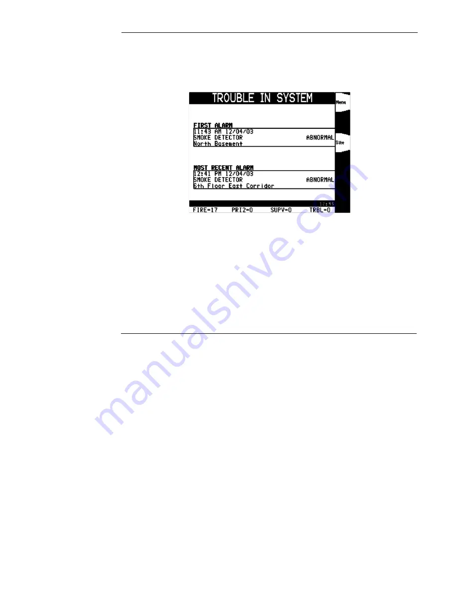
Unlock and open the enclosure door.  The display shows the trouble condition.  For example:

 Figure 3-3. Trouble Display

2.

Press the TROUBLE ACK key.  An alarm list opens. Every flashing report indicates an 
unacknowledged trouble condition. Continue pressing the TROUBLE ACK key and reading 
the reports until all reports have been acknowledged. Once all reports have been acknowledged 
the tone-alert silences and the LED glows steady.

3.

Read the display.  Investigate the trouble to determine its cause.  Make necessary repairs in 
accordance with the manufacturer's instructions. When the trouble clears, the Trouble LED 
flashes and the tone-alert sounds steady.

4.

Press the TROUBLE ACK key.  The display shows the system status.  Press the 
TROUBLE ACK key again.  After a delay, the display shows that the system status is normal.

firealarmresources.com

Содержание InfoAlarm 4100ES

Страница 1: ...Operator s Manual Part InfoAlarm Product 4100U 4100ES 579 685 Rev B firealarmresources com ...

Страница 2: ...ii firealarmresources com ...

Страница 3: ...iii firealarmresources com ...

Страница 4: ... may exceed eye safety limits Do not use magnification such as a microscope or other focusing equipment when viewing the output of this device FCC RULES AND REGULATIONS PART 15 This equipment has been tested and found to comply with the limits for a Class A digital device pursuant to Part 15 of the FCC Rules These limits are designed to provide reasonable protection against harmful interference wh...

Страница 5: ...s 2 5 Individually Acknowledging Alarms 2 6 Silencing an Alarm 2 7 Overview 2 7 Using the Alarm Silence Key 2 8 Resetting the System 2 9 Overview 2 9 Resetting a System with Active Alarms 2 9 Performing a Hardware Reset 2 10 Chapter 3 Trouble Conditions 3 1 Introduction 3 1 In this Chapter 3 1 Overview 3 2 How the FACP Indicates the Presence of a Trouble 3 2 What an Acknowledge Does 3 2 Acknowledg...

Страница 6: ...apter 6 Advanced Functions 6 1 Introduction 6 1 In this Chapter 6 1 Logging In and Out of the System 6 2 Introduction 6 2 Procedure 6 2 Log Out Procedure 6 2 Setting System Time and Date 6 3 Overview 6 3 Procedure 6 3 Viewing the Time at which an Event Occurred 6 4 Overview 6 4 Procedure 6 4 Enabling and Disabling Points 6 5 Overview 6 5 Procedure 6 5 Forcing Points On and Off 6 6 Overview 6 6 For...

Страница 7: ...Being Evacuated 8 5 Page Additional Floors 8 5 Listen to What is Being Played Using the Local Speaker 8 6 Silencing the Audio System 8 6 Resetting the Audio System 8 6 Two Channel Audio Operation 8 7 Overview 8 7 Evacuate Entire Building 8 7 Evacuate Specific Floors when No Alarms are Present 8 8 Evacuate Additional Floors During an Alarm 8 8 Alert Specific Floors 8 8 Evacuate Floors On Which Aler...

Страница 8: ...ic Floors 8 12 Listen to What is Being Played on the EVAC Channel Using the Local Speaker 8 12 Listen to What is Being Played on the Alert Channel Using the Local Speaker 8 12 Silencing the Audio System 8 12 Resetting the Audio System 8 12 firealarmresources com ...

Страница 9: ...s or characters that you type Unless it is spe cifically noted you can type the text in lowercase or upper case characters For example cd access means that you type the lowercase letters cd followed by a space and the lowercase word access Italic type Indicates information that the user must supply such as file names For example cd directory_name means that you type the letters cd followed by a sp...

Страница 10: ...firealarmresources com ...

Страница 11: ...with 4100U and 4100ES Fire Alarm Control Panels FACP and describes the normal appearance of the Flexible User Interface panel In this Chapter Refer to the page number listed in this table for information on a specific topic Topic See Page Basic System Description 1 2 Normal Appearance of Operator Interface Panel 1 4 firealarmresources com ...

Страница 12: ...s a generic term used to refer to an individual component of the system such as a single smoke detector or a single pull station The FACP operator interface shown in Figure 1 1 allows a system operator to control and monitor the facility specific components connected to the FACP Figure 1 1 Flexible User Interface Controls Facility Specific Control Keys and LEDs Fire Alarm LED and ACK Key Priority ...

Страница 13: ...icate that you have observed the presence of a trouble Alarm Silenced LED Alarm Silence Key Pressing the ALARM SILENCE key provides a means of silencing the building s audible notification appliances horns The LED indi cates when this key has been used System Reset Key Pressing this key directs the panel to reset all attached devices and clear all acknowledged alarms troubles and supervisory condi...

Страница 14: ...pecific control keys and the customizable LEDs The multi line LCD shows either a text screen indicating normal operation see Figure 1 2 or a sitemap see Figure 1 3 Figure 1 2 Normal Operation Text Screen Figure 1 3 Normal Operation Sitemap Screen Note If the appearance of the operator interface panel is not as shown above refer to the information in Chapters 2 3 and 4 for instructions on managing ...

Страница 15: ... this table for information on a specific topic Acknowledging an Alarm How the FACP Indicates that an Alarm has Occurred When an alarm condition is detected by the FACP the panel does the following to indicate the pres ence of the alarm The red LED and the labeled Fire Alarm flashes The tone alert piezo buzzer pulses The LEDs on the remote annunciators may illuminate The LCD on the interface panel...

Страница 16: ...t display has been selected the first 5 alarm situations will appear on the screen followed by the most recent Each alarm report displays the custom label followed by the point type starting with the first alarm and moving down the list until the fifth and finishing with the most recent If fewer than 5 devices report an alarm condition the most recent device appears in the most recent alarm space ...

Страница 17: ...hed to at any time by pressing the Site softkey Points for a FACP system can be placed on the sitemap in the FACP Programmer In an alarm mode the icon representing the point reporting the alarm flashes The icon flashes as long as it goes unacknowledged Once the point has been acknowledged the icon ceases to flash and remains steady If a point close to an unac knowledged point reports an alarm cond...

Страница 18: ...elected by pressing and holding the More info softkey The time of the alarm occurence is displayed by pressing and holding the Event Time softkey All unacknowledged alarms entries flash until acknowledged Figure 2 5 Direct to Alarm List Display General Status Message A general status message display appears in a text box In the centre of the screen a message indicates the alarm status Upon acknowl...

Страница 19: ...n alarm status This is helpful when a series of devices enter an alarm state for example all of the smoke detectors in an area of the building and you want to acknowledge all of them at the same time Individual acknowledge If individual acknowledge is enabled the ALARM ACK key must be pressed to individually acknowledge each alarm Individual acknowledge must be selected if the panel is providing p...

Страница 20: ...Use the following procedure if the Individual Acknowledge option is enabled on your FACP system 1 Unlock and open the enclosure door Read the display on the interface panel It reports the number of alarm conditions at the bottom of the screen as shown below Figure 2 9 Bottom of LCD 2 Press the ALARM ACK key Read and follow the instructions on the display Refer to Figure 2 8 3 Press the ALARM ACK k...

Страница 21: ...he ALARM SILENCE function If a Coded Input Device typically a pull station activates the ALARM SILENCE key may be ignored until this function has completed coding Notification appliances horns cannot be silenced when a coded station is in alarm but will silence upon coding completion If the Alarm Silence Inhibit Option which is a timer that inhibits the operation of the ALARM SILENCE function is e...

Страница 22: ... alarms are present attempts to return the system to its normal state This includes resetting initiating devices pull stations and smoke detectors for example relays including city relay and door holder relays notification appliances horns and strobes and all LEDs and indicators that have been programmed to be reset with the SYSTEM RESET key See Resetting a System with Active Alarms below for more...

Страница 23: ...eps to perform a system reset when alarms are present 1 Press the SYSTEM RESET key The following message appears Figure 2 11 System Reset Information Box 2 One of the following occurs depending on whether the activated devices reset or not If all zones or devices in alarm reset the SYSTEM ALARM LED flashes Press the ALARM ACK key and the following message appears Figure 2 12 Normal Operation Text ...

Страница 24: ...n the alarm condition Read the display to determine the type and location of the device Follow local procedures to investigate the area of the building in alarm Look for devices that are in an alarm state like pull stations with the handle down or smoke detectors with their LED lit Performing a Hardware Reset A hardware reset re initializes the state of certain hardware components and is typically...

Страница 25: ...il ure to correct trouble conditions may compromise the detection and report of an emergency condition This chapter describes using the operator interface panel keys to investigate the details of the trouble condition In this Chapter Refer to the page number listed in this table for information on a specific topic Topic See Page Overview 3 2 Acknowledging Troubles 3 3 If the Trouble Doesn t Clear ...

Страница 26: ...gs It records the time and date at which you observed the presence of the trouble and stores that information in the system s historical log When you press the acknowledge key the system displays specific data on the location of the trouble The FACP can be configured with either global or individual acknowledge These options function as follows Global Acknowledge When global acknowledge is enabled...

Страница 27: ...e last button pressed 1 Unlock and open the enclosure door The display shows the trouble condition For example Figure 3 2 Trouble Display 2 Press the TROUBLE ACK key under the flashing yellow LED The display shows a list of all devices in a trouble condition The tone alert silences and the yellow LED glows steady 3 Read the display and investigate the area to determine the cause of the trouble a R...

Страница 28: ...alarm list opens Every flashing report indicates an unacknowledged trouble condition Continue pressing the TROUBLE ACK key and reading the reports until all reports have been acknowledged Once all reports have been acknowledged the tone alert silences and the LED glows steady 3 Read the display Investigate the trouble to determine its cause Make necessary repairs in accordance with the manufacture...

Страница 29: ...e trouble cannot be located call an authorized Simplex representative to repair the system System Reset Key Some troubles latch until they are reset manually or are reset by pressing the SYSTEM RESET key Try pressing the SYSTEM RESET key if the trouble is any one of the following Class A initiating device circuit trouble City Circuit trouble 24 Point I O trouble If pressing the SYSTEM RESET key do...

Страница 30: ...susceptible to false alarms In addition to the two automatic trouble conditions the FACP software includes a pre programmed digital pseudo point P132 Sensor Almost Dirty Log Enable that can be selected through the ES PC Programmer application When selected a system log entry is genereated when a sesnor is Almost Dirty This feature is used to facilitate maintenance by providing a log of sensors tha...

Страница 31: ...other system used for the protection of life and property This chapter describes using the operator interface panel keys to investigate the details of the supervisory condition In this Chapter Refer to the page number listed in this table for information on a specific topic Topic See Page Overview 4 2 Acknowledging Supervisory Conditions 4 3 firealarmresources com ...

Страница 32: ...e yellow LED labeled SUPERVISORY flashes The tone alert piezo buzzer sounds steady The LCD on the interface panel indicates a supervisory condition There are six ways that the Flexible User Interface can display a supervisory condition Refer to Chapter 2 for descriptions of the six display modes An example is shown below Figure 4 1 First 5 Last Display for Supervisory Conditions firealarmresources...

Страница 33: ...rvisory Conditions Pressing the SUPV ACK key once globally acknowledges all supervisory conditions that exist within the fire alarm system In addition the SUPERVISORY LED changes from flashing to steady ON and the tone alert silences If global acknowledge is enabled on your system use the following procedure to acknowledge the supervisory conditions 1 Unlock and open the enclosure door The display...

Страница 34: ...to Figure 4 1 2 Press the SUPV ACK key Repeat this step and read the reports The display shows the area and type of condition The tone alert silences and the yellow LED glows steady 3 Read the display Investigate the problem to determine its cause When the problem causing the condition is corrected the SUPERVISORY LED flashes and the tone alert sounds steady 4 Press the SUPV ACK key The display sh...

Страница 35: ...ervisory list Using the Entry Keys The entry keys located on the far right of the operator interface contain abbreviated labels for each category of point For example the key in the upper left corner of the entry keys is labeled ZONE and the key to its right is labeled SIG Pressing one of these keys causes the system to prompt you to select a specific point within the selected category In this Cha...

Страница 36: ...e lists can be selected as follows 1 Press the appropriate acknowledge key to enter the list For example press the FIRE ALARM ACK key to enter the list of current fire alarms or press the TROUBLE ACK key to enter the list of current troubles 2 Use the NEXT and PREV keys to scroll through the entries in this list Stop scrolling when the point you are interested in is highlighted 3 Press the More In...

Страница 37: ...tion Appliance Circuit NAC and is number from 3 to n n represents the number of the last signal point in your system After selecting a signal point use NEXT and PREV to scroll through the signal points AUX allows you to select an Auxiliary Relay AUX where AUX represents an auxiliary relay and is a number from 3 to n n represents the number of the last auxiliary relay in your system FB allows you t...

Страница 38: ... the point in the system Specify the address using the format C P S where C is the card P is the point and S is the subpoint You must insert the dash between the com ponents of the address Use the NET key to enter the dash Key Data to Enter Action Description Full Label Shows the entire custom label on the line Release the button to revert back to the standard format Enable Enables the selected po...

Страница 39: ...to the page number listed in this table for information on a specific topic Topic See Page Logging In and Out of the System 6 2 Setting System Time and Date 6 3 Viewing the Time at which an Event Occurred 6 4 Enabling and Disabling Points 6 5 Forcing Points On and Off 6 6 Displaying and Clearing Historical Logs 6 7 Printing Reports 6 8 firealarmresources com ...

Страница 40: ... door 1 Obtain the passcode for the access level at which you want to operate 2 Press MENU on the entry keypad located on the right side of the interface panel 3 Press the direction keys until the cursor highlights Access Press ENTER or the Select Item softkey 4 Scroll the cursor to the Login command and press ENTER or the Select item softkey The following screen appears Figure 6 1 Login screen 5 ...

Страница 41: ...y shows the option for setting time and date 2 Press the ENTER key The system responds as follows Figure 6 2 The Set Date Screen 3 The display shows the current date followed by a the new date filled by blank underlined characters Use the entry keys to enter the new date or press ENTER to leave the date unchanged 4 The next screen displays the time in a similar format to the Figure 6 2 Use the ent...

Страница 42: ...EVENT TIME key Refer to the procedure below for information on doing this Procedure 1 Select the alarm trouble or supervisory event whose event time you want to display To do this follow these steps a Press the FIRE ALARM ACK PRIORITY 2 ACK TROUBLE ACK or SUPERVISORY ACK key to enter the appropriate list of events For example press the FIRE ALARM ACK key to enter the list of active fire alarms b U...

Страница 43: ...int and during the time the point is disabled a custom control equation executes that turns the point ON This action is suspended for the duration of time the point is disabled However when the point is subsequently enabled the point s state updates and the custom control equation turning the point ON executes turning the signal ON Procedure Follow these steps to enable or disable a point 1 Select...

Страница 44: ...formation on selecting points 2 Press the Select Item softkey or press ENTER to access the point 3 Scroll down to show the various softkey operations 4 Press either the On or Off softkey The system indicates that the command has been accepted and generates a Manual Override Trou ble for the point to remind you that the point has been forced ON or OFF Returning a Point to Automatic Operation Automa...

Страница 45: ...ince the last time the logs were cleared Historical Trouble Log Provides detailed information on each trouble including time and date stamp that has occurred since the last time the logs were cleared Displaying Clearing Historical Logs 1 Press the MENU key Use the NEXT and PREVIOUS keys to scroll through the choices until the DISPLAY HISTORICAL ALARM LOG or DISPLAY HISTORICAL TROUBLE LOG choice is...

Страница 46: ...d date device experienced trouble TrueAlarm Status Report Reports the following information for each point Device Custom Label Current Sensitivity of the Point Point Status Normal Trouble Alarm Almost Dirty Status Points which are almost dirty have an asterisk in this field to denote this TrueAlarm Service Report Reports the following information for each point Device Custom Label Alarm Level sens...

Страница 47: ... describes the system tests that can be performed from the front panel of the FACP In this Chapter Refer to the page number listed in this table for information on a specific topic Topic See Page WalkTest Overview 7 2 Setting WalkTest Options 7 3 firealarmresources com ...

Страница 48: ... device the system s signals pulse a code that allows you to verify exactly which initiating device triggered the sig nals For hardwired monitor zones the signal code corresponds to the number of the zone For example if the zone number is eight the signals pulse eight times to indicate zone eight For IDNet and MAPNET devices the first set of pulses from the signals correspond to the channel The si...

Страница 49: ...w points to LOG logging is enabled If the arrow points to NO logging is disabled Press 2 on the keypad to toggle the setting of this option Coding When ZONE is selected the signals play a code that indicates the activated initiating device s address For hardwired zones the signals sound the number of the zone For IDNet and MAPNET the code has two parts separated by a pause The first part indicates...

Страница 50: ...firealarmresources com ...

Страница 51: ...ng a pre recorded message when a specific button is pressed For example you may press a button to play an attention tone and phrase before using the microphone to make a live audio announcement Live Audio Microphones connected to the audio system allow operators to issue live announcement messages In this Chapter Refer to the page number listed in this table for information on a specific topic Top...

Страница 52: ... at a time Figure 8 1 Single Channel Audio Continued on next page FACP MAIN CONTROL PANEL FIRE ALARM SILENCED LED FIRE ALARM SILENCED KEY RED FIRE ALARM LED FIRE ALARM ACKNOWLEDGE KEY TALK LED MIKE TALK SWITCH IN CONTROL ALL SPEAKERS EVAC SELECTIVE EVAC READY TO TALK ALL SPEAKERS TALK LOCAL SPEAKER EVAC 8th Flr 7th Flr 6th Flr 5th Flr 4th Flr 3rd Flr 2nd Flr 1st Flr PHONE PIEZO SILENCE PHONE 8 CIR...

Страница 53: ...s During an Alarm When a fire alarm occurs the evacuation message automatically plays on specific floors but other areas of the building may not automatically play the message Additional floors can be evacuated as follows 1 Press the speaker circuit button s for the additional floors When you do this the LEDs for the selected floors illuminate and the message plays on the speaker circuits for thos...

Страница 54: ...hear what is being played at that time The LED asso ciated with this button illuminates when the button is pressed to indicate the function is active Note If the user picks up the local phone or keys the microphone while the local speaker is active the speaker shuts off to prevent feedback The local speaker turns back on when the page is complete Silencing the Audio System Press the Alarm Silence ...

Страница 55: ...n a fire alarm occurs the evacuation message automatically plays on specific floors but other areas of the building may not automatically play the message Additional floors can be evacuated as follows 1 Press the speaker circuit button s for the additional floors When you do this the LEDs for the selected floors illuminate and the message plays on the speaker circuits for those floors Note The eva...

Страница 56: ...one while the local speaker is active the speaker shuts off to prevent feedback The local speaker turns back on when the page is complete Silencing the Audio System Press the Alarm Silence button on the front panel to silence the audio system When you do this the speakers remain on but play nothing Resetting the Audio System Press the System Reset button to reset the audio system When you do this ...

Страница 57: ...es as do the LEDs for each of the speaker circuits floors Continued on next page FACP MAIN CONTROL PANEL FIRE ALARM SILENCED LED FIRE ALARM SILENCED KEY RED FIRE ALARM LED FIRE ALARM ACKNOWLEDGE KEY TALK LED MIKE TALK SWITCH IN CONTROL ALL SPEAKERS EVAC LOCAL SPEAKER EVAC ALL SPEAKERS TALK LOCAL SPEAKER ALERT 8th Flr 7th Flr 6th Flr 5th Flr 4th Flr 3rd Flr 2nd Flr 1st Flr OPERATION SELECT SWITCHES...

Страница 58: ...age begins at whatever point it is currently at For example the entire message may be Please evacuate this Floor Proceed to your designated assembly area If you press the speaker circuit when the message is half through only the second half of the message will play on the additional speaker circuit Alert Specific Floors Follow these steps to play the Alert message on specific floors areas of the b...

Страница 59: ...he buttons associated with the additional floors The LEDs associated with these floors turn ON and the page is heard on their speaker circuits Listen to What is Being Played on the EVAC Channel Using the Local Speaker Press the button labeled Local Speaker to hear what is being played on the EVAC channel at that time The LED associated with this button illuminates when the button is pressed to ind...

Страница 60: ...IRE ALARM SILENCED KEY RED FIRE ALARM LED FIRE ALARM ACKNOWLEDGE KEY TALK LED MIKE TALK SWITCH IN CONTROL ALL SPEAKERS EVAC LOCAL SPEAKER EVAC ALL SPEAKERS TALK LOCAL SPEAKER ALERT 8th Flr 7th Flr 6th Flr 5th Flr 4th Flr 3rd Flr 2nd Flr 1st Flr OPERATION SELECT SWITCHES SPEAKER SELECT SWITCHES SPEAKER SELECT SWITCHES PHONE SELECT SWITCHES SELECTIVE EVAC READY TO TALK 8th Flr 7th Flr 6th Flr 5th Fl...

Страница 61: ...ation message begins at whatever point it is currently at For example the entire message may be Please evacuate this Floor Proceed to your designated assembly area If you press the speaker circuit when the message is half through only the second half of the message will play on the additional speaker circuit Alert Specific Floors Follow these steps to play the Alert message on specific floors area...

Страница 62: ...the LEDs on the display card light and the announcement plays over the speakers Listen to What is Being Played on the EVAC Channel Using the Local Speaker Press the button labeled Local Speaker to hear what is being played on the EVAC channel at that time The LED associated with this button illuminates when the button is pressed to indicate the function is active Note If the user picks up the loca...

Страница 63: ...firealarmresources com ...

Страница 64: ...579 685 Rev B firealarmresources com ...

Отзывы: