SL-889 HDMI 2.1 Cat-3 Cable EMI Tester
User Guide
14
© 2019-2020 Simplay Labs, LLC.,
Simplay-UG-SL889-1.1
All rights reserved. CONFIDENTIAL
5.
Attach an HDMI cable
from HDMI OUT1 to HDMI IN1. The second line of the LCD will transition from “Searching…”
to an informational message
(ex: “
TMDS
185 MHz”) wh
en a link has been successfully connected. The unit is now
ready for EMI scans to be taken.
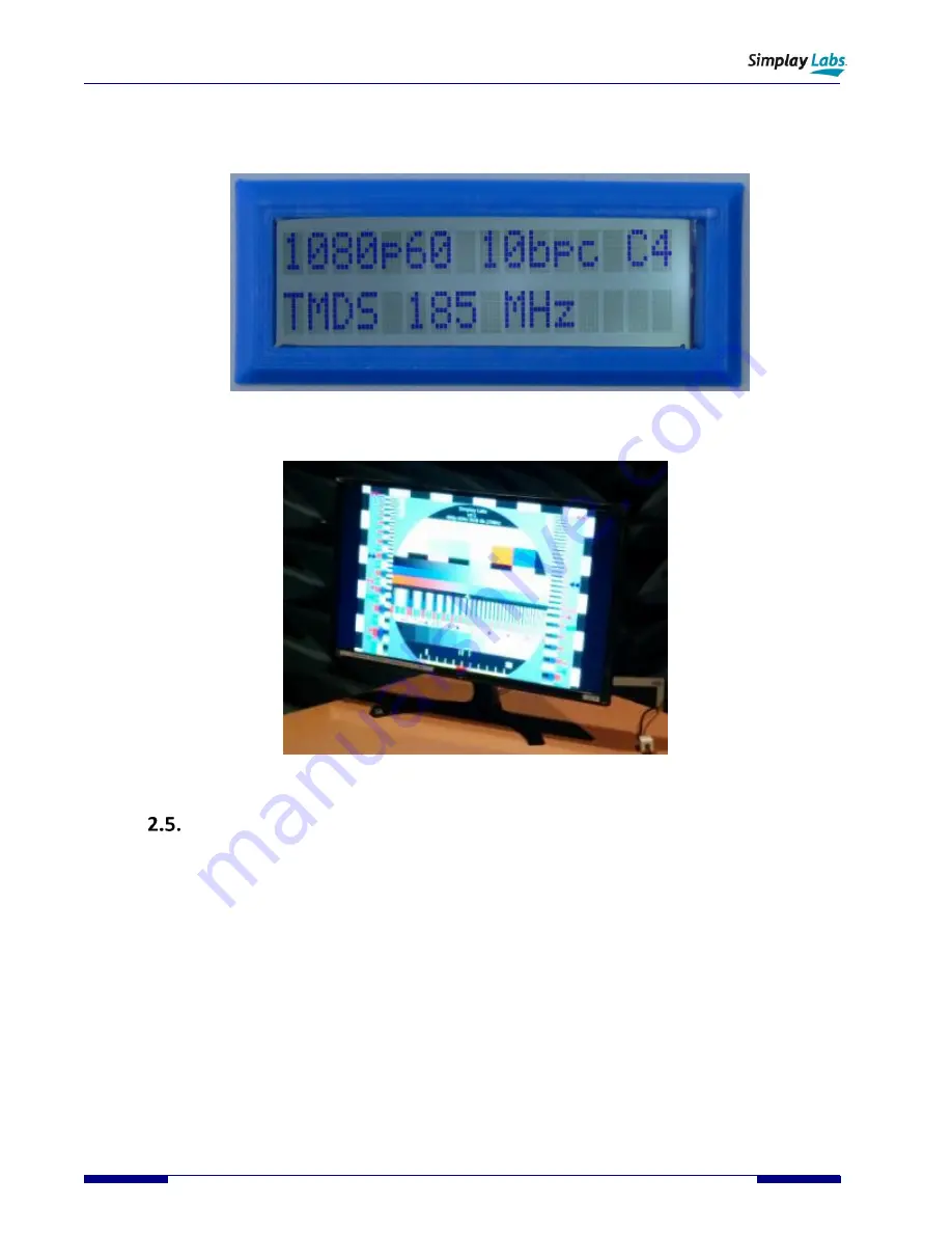
Figure 2.7. SL-889 Operation: C4 Resolution, TMDS 185 MHz link, HDMI Cable Attached
6.
Attach an optional HDMI monitor to HDMI OUT2 to display the ITU BT1729 test pattern.
Figure 2.8. SL-889 Operation: Optional Monitor Output
Operation
–
Quick Start
Pre-test Setup:
1.
Attach the +12V power supply to the unit. You will hear the internal fans if you listen closely.
2.
The LCD lights up and displays a boot down count screen as it powers up.
3.
After the internal boot counts completes, the LCD will change to show the last resolution selected.
4.
The selector knob chooses between 16 different resolutions.
5.
Rotate the selector knob to choose the desired resolution.
6.
The LCD screen shows “C0” – “C15” in the upper right.
7.
Attach an optional 4K monitor to the HDMI OUT2 output connector.
8.
Attach a DUT cable between the HDMI OUT1 output and HDMI IN1 input connectors.
9.
The
ITU
-R
BT.1729
. (2005). Common 16:9 or 4:3 aspect ratio digital television reference test pattern should
appear on the monitor.
Note: Monitor output
is only available if a DUT cable is attached
. (See Signal Path diagram)
Taking Scans:
10.
Disconnect the Monitor from the SL-889 HDMI OUT2 output, and unplug it.


