

2899
7
GB
4.3
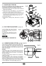
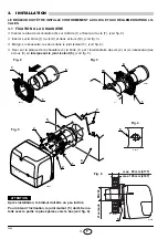
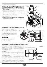
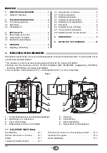
MAINTENANCE POSITION
Access to the combustion head, the diffuser disc-hold-
er assembly, electrodes and nozzle, (see fig. 14).
➤
Remove the burner out of the boiler, after loosing the
fixing nut to the flange.
➤
Hook the burner to the flange (1), by removing the
blast tube (2) after loosing the fixing screws (3).
➤
Remove the small cables (4) from the electrodes and
the diffuser disc-holder assembly (6) from the nozzle-
holder (5) after loosing its fixing screw (3, fig. 15).
➤
Screw the nozzle (7).
➤
Reassemble, following these instructions in reverse
order.
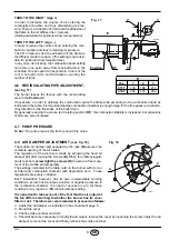
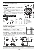
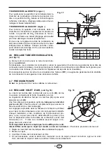
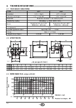
4.4
ELECTRODES ADJUSTMENT,
(see fig. 15)
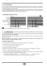
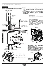
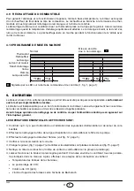
4.5
COMBUSTION HEAD SETTING,
(see figs. 16 and 17)
This is done when fitting the nozzle, with the blast tube re-
moved. It depends on the output of the burner and is car-
ried out by rotating the regulating rod, till the terminal
plane of the blast tube is level with the set-point, as indi-
cated in the schedule.
Example
In the sketch on fig. 16, the combustion head is set for an
output of 0.60 GPH at 12 bar for the burner type 417T,
while the shutter is level with set-point 2, as required by
the above schedule.
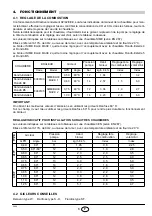
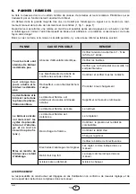
Combustion head settings indicated in the schedule are
valid for most cases.
The setting of the fan output according to the installation
should normally be done only through the air damper.
Should one subsequently want to retouch also the setting
of the combustion head, with the burner running, operate
on the rod (1) with a 6 mm spanner (2), (see fig. 17).
E9136
Fig. 14
2
3
5
1
6
4
7
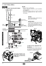
MEASURES MUST BE RESPECTED.
WARNING
D6049
4
5
3
1
4.5
– 0.5 mm
0
2
–
2.5
mm
5.5 ±
0.3 mm
2
Fig. 15
Lean the diffuser disc-holder assembly
(1) on the nozzle-holder (2) and lock it
by screw (3).
For prospective adjustments loosen
screw (4) and move the electrodes as-
sembly (5).
3
5
6
4
2
0
3
D5589
Blast tube
Shutter
Terminal plane of the blast tube
Regulating rod
Fig. 16