background image


2899


3


GB


3.

INSTALLATION


THE BURNER MUST BE INSTALLED IN CONFORMITY WITH LEGISLATION AND LOCAL STANDARDS.


3.1

BOILER FIXING


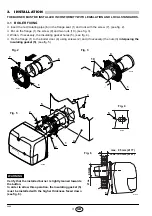
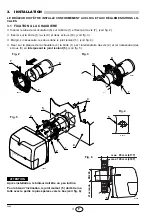
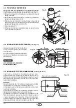
Insert the recirculating pipe (6) in the flange seat (1) and lock with the screw (7), (see fig. 2).


Put on the flange (1) the screw (9) and two nuts (10), (see fig. 3).


Widen, if necessary, the insulating gasket holes (5), (see fig. 4).


Fix the flange (1) to the boiler door (4) using screws (2) and 


(if necessary)


 the nuts (3) 


interposing the

insulating gasket (5)


, (see fig. 5).


Verify that the installed burner is lightly leaned towards
the button.
In order to allow this operation, the insulating gasket (5)
must be installed with the higher thickness faced down
(see fig. 6).

WARNING

E9051

1

7

E9055

E9056

D1959

max. 95 mm (417T)

max. 105 mm (418T)

D5012

5

Fig. 4

1

Fig. 3

9

10

1

2

2

5

Fig. 5

4

3

Fig. 2

ø


as

Fig. 6

EN226

6

5

Содержание SIME BLUE MACK 1

Страница 1: ...tretien Installatie gebruiks en onderhoudsvoorschriften Light oil burners Br leurs fioul Stookoliebranders CODE MODEL MODELE TYPE 8099100 SIME BLUE MACK 1 417 T 8099105 SIME BLUE MACK 2 418 T GB F NL...

Страница 2: ...G 6 4 1 Combustion adjustment 6 4 2 Nozzles recomended 6 4 3 Maintenance position 7 4 4 Electrode adjustment 7 4 5 Combustion head setting 7 4 6 Recirculating pipe adjustment 8 4 7 Pump pressure 8 4 8...

Страница 3: ...2850 rpm 298 rad s Capacitor 4 F Ignition transformer Secondary 8 kV 16 mA Pump Pressure 7 15 bar Absorbed electrical power 0 18 kW 0 23 kW O H 4 5 F B 11 D D6085 M N N P 4 5 L D5908 TYPE A B C D E F...

Страница 4: ...insulating gasket holes 5 see fig 4 Fix the flange 1 to the boiler door 4 using screws 2 and if necessary the nuts 3 interposing the insulating gasket 5 see fig 5 Verify that the installed burner is...

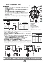
Страница 5: ...the same level as the suction line In this case a non return valve is not required Should however the return line arrive over the fuel level a non return valve is required This solution however is le...

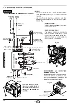
Страница 6: ...r 230V 0 1A max Limit thermostat Remote lock out signal Ignition electrodes Start thermostat Heater L N PE Motor Main switch Safety thermostat E9116 A Fig 11 B For burners installed on air generators...

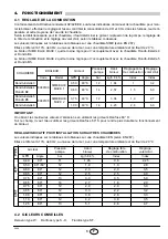
Страница 7: ...et the best emission values In field it is advisable to use Danfoss 60 S nozzles in order to make the burner working more reliable in time APPROXIMATE ADJUSTMENTS FOR INSTALLATION ON OTHER BOLERS The...

Страница 8: ...of the blast tube is level with the set point as indi cated in the schedule Example In the sketch on fig 16 the combustion head is set for an output of 0 60 GPH at 12 bar for the burner type 417T whil...

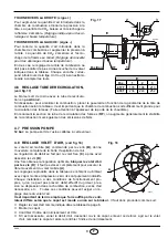
Страница 9: ...ity is increased but emissions of NOx are also increased 4 7 PUMP PRESSURE 12 bar The pump leaves the factory set at this value 4 8 AIR DAMPER ADJUSTMENT see fig 18 The mobile air damper A operated by...

Страница 10: ...avoiding the excessive consumption of fuel and consequent pollution Before carrying out any cleaning or control always first switch off the electrical supply to the burner acting on the main switch of...

Страница 11: ...USES SOLUTION All led are off and the burner does not start Lack of electrical supply Check presence of voltage in the L1 N clamps of the 7 pin plug Check the conditions of the fuses Check that safety...

Страница 12: ...dements lectriques 5 4 FONCTIONNEMENT 6 4 1 R glage de la combustion 6 4 2 Gicleurs conseill s 6 4 3 Positionnement des lectrodes 6 4 4 R glage t te de combustion 7 4 5 Pression de la pompe 7 4 6 R gl...

Страница 13: ...b s 2850 t min 298 rad s Condensateur 4 F Transformateur d allumage Secondaire 8 kV 16 mA Pompe Pression 7 15 bar Puissance lectrique absorb e 0 18 kW 0 23 kW H F B D D6085 I G A E C O 4 5 11 M N N P...

Страница 14: ...ous dans le joint isolant 5 voir fig 4 Fixer sur la plaque de la chaudi re 4 la bride 1 par l interm diaire des vis 2 et si n cessaire des crous 3 en interposant le joint isolant 5 voir fig 5 E9051 1...

Страница 15: ...a pr c dente en raison du man que d tanch it ventuel de ce clapet H m tres L m tres i 8 mm i 10 mm 0 5 1 1 5 2 10 20 40 60 20 40 80 100 H m tres L m tres i 8 mm i 10 mm 0 0 5 1 1 5 2 3 3 5 35 30 25 20...

Страница 16: ...ctriques ex cut s par l ins tallateur doivent respecter le r glement en vigueur dans le Pays PE ACCESSIBILITE AU DETECTEUR FLAMME voir fig 12 Le d tecteur flamme est mont directe ment sur la bo te de...

Страница 17: ...nfoss 60 H Sur le champ il vaut mieux utiliser les gicleurs Danfoss 60 S pour rendre plus durable le fonctionnement du br leur REGLAGE INDICATIF POUR INSTALLATION SUR AUTRES CHAUDIERES Les valeurs ind...

Страница 18: ...rd concorde avec l encoche indi qu e dans le tableau Exemple Dans le dessin de fig 16 la t te est r gl e pour un d bit de 0 60 GPH 12 bar pour le br leur type 417T L obturateur est en effet dans la po...

Страница 19: ...combustion mais galement les missions de NOx 4 7 PRESSION POMPE 12 bar La pompe sort de l usine calibr e cette valeur 4 8 REGLAGE VOLET D AIR voir fig 18 Le volet d air mobile A command par le v rin...

Страница 20: ...mbustible excessives et donc les missions d agents polluants Avant chaque op ration de nettoyage ou de contr le couper l alimentation lectrique en agissant sur l interrupteur g n ral LES OPERATIONS ES...

Страница 21: ...limentation lectrique V rifier la tension au bornier L1 N de la fiche 7 p les V rifier les fusibles V rifier que le thermostat de s curit ne soit pas intervenu Les branchements de la bo te de contr le...

Страница 22: ...eling verbranding 6 4 2 Aangewezen verstuivers 6 4 3 Onderhoudspositie 7 4 4 Afstelling electroden 7 4 5 Afstelling verbrandingskop 7 4 6 Afstelling recirculatieleiding 8 4 7 Pompdruk 8 4 8 Regeling v...

Страница 23: ...nomen stroom 0 80A 2850 t min 298 rad s Condensator 4 F Ontstekingstransformator Secundair 8 kV 16 mA Pomp Druk 7 15 bar Opgeslorpt vermogen 0 18 kW 0 23 kW H F B D D6085 I G A E C O 4 5 11 M N N P 4...

Страница 24: ...Indien nodig de gaten in de flensdichting 5 zie fig 4 vergroten Bevestig de flens 1 op de ketelplaat 4 met behulp van de schroeven 2 en indien nodig de moeren 3 en voeg de flensdichting 5 ertussen zie...

Страница 25: ...tweede oplossing biedt echter minder zekerheid omdat de dichtheid van de voetklep eventueel ontoereikend kan zijn H meter L meter i 8 mm i 10 mm 0 5 1 1 5 2 10 20 40 60 20 40 80 100 H meter L meter i...

Страница 26: ...ax Ontstekings electroden Regelthermostaat Voorverwarmer L N NULLEIDER EN FASE NIET OMWISSELEN OPGELET NOOT Doorsnede geleiders min 1 mm2 Mits anders voorgeschreven door plaatselijke nor men en wetten...

Страница 27: ...e emissiewaarden verkregen Er wordt aangeraden Danfoss 60 S verstuivers te gebruiken zodat de brander langer betrouwbaar werkt INDICATIEVE AFSTELLING VOOR INSTALLATIE OP ANDERE KETELS De in de tabel v...

Страница 28: ...de branderkop overeen komt met het in de tabel weergegeven streepje Voorbeeld In de schets van fig 16 is de kop afgesteld voor een debiet van 0 60 GPH bij 12 bar op een brander type 417T Het streepje...

Страница 29: ...de NOx emissies toe 4 7 POMPDRUK 12 bar De pomp verlaat de fabriek afgesteld op deze waarde 4 8 REGELING VAN DE LUCHTKLEP zie fig 18 De beweegbare luchtklep A die door de vijzel B bediend wordt opent...

Страница 30: ...om uitermate hoog brandstofverbruik en dus hoge milieubelastende emissies te vermijden Alvorens de brander te reinigen of te controleren sluit de elektrische voeding af door op de hoofd schakelaar te...

Страница 31: ...che voeding Geen stroom Check de spanning aan het klemmen bord L1 N van de 7 polige mannelijke stekker Check de zekeringen Check of de thermostaat niet vergrendeld is De aansluitingen van de controled...

Страница 32: ...Fonderie Sime S p A via Garbo 27 37045 Legnago Vr Italy Tel 39 0442 631111 Export Division fax number 39 0442 631293 Sime Service fax number 39 0442 631292...

Отзывы: