18
3 .4
EXTERNAL SENSOR
CONNECTED (fig . 13)
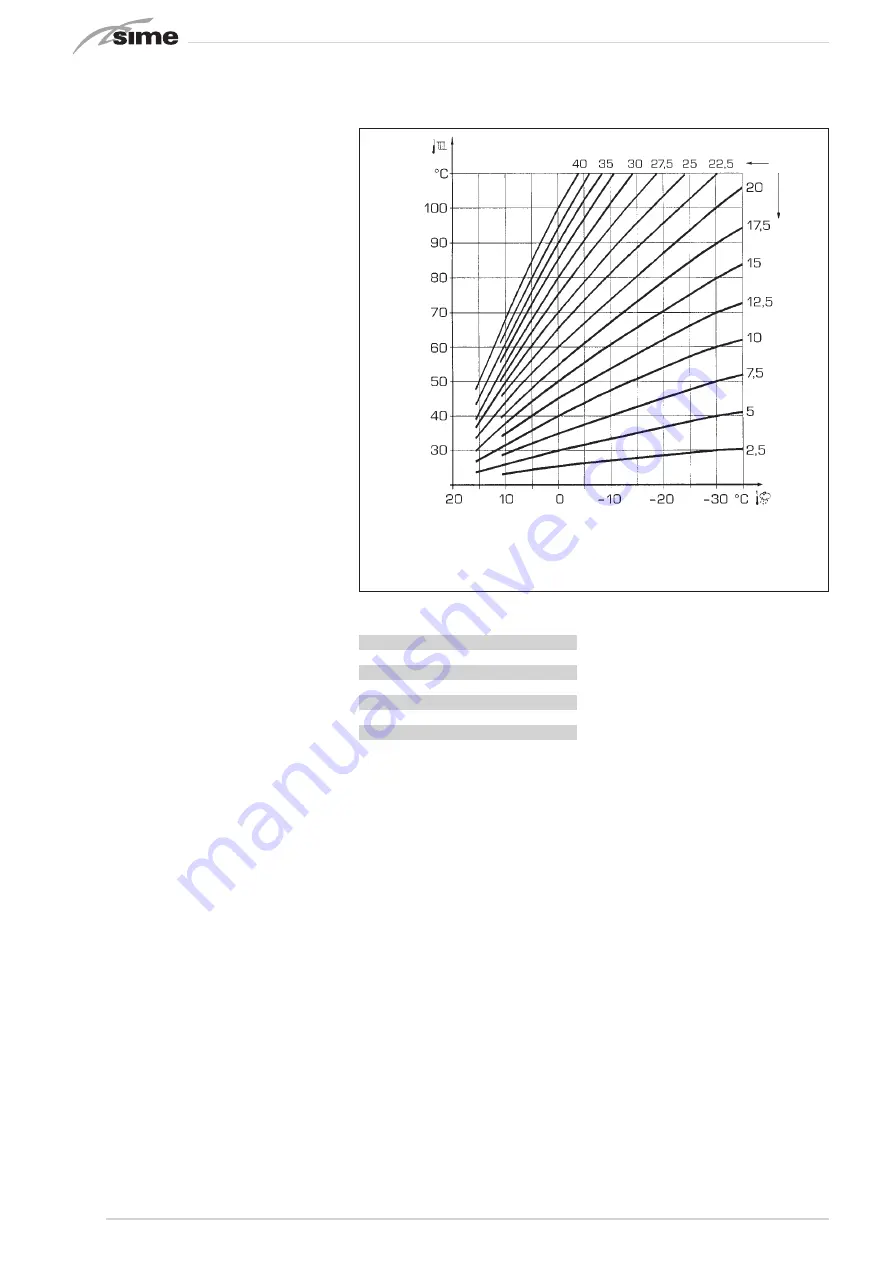
If an external sensor is connected, the
heating setpoints can be derived from
the climatic curves as a function of the
external temperature, within the range
described in par. 3.3 (PAR 22 for zone 1,
PAR 25 fro zone 2 and PAR 28 for zone 3).
The climatic curve can be chosen from the
range 3 to 40 (in steps of 1). Increasing
the slope shown in fig. 13 increases the
delivery temperature as a function of the
external temperature.
3 .5
CONTROLLER FUNCTIONS
The electronic controller has the follow-
ing functions:
– Heating and DHW circuit anti-freeze
protection (ICE) .
– Flame ignition and detection.
– Control panel adjustment of the boil-
er’s power and gas.
– Anti-locking function: runs the pump
for a few seconds every 24 hours of
disuse.
– Anti-legionella function for storage
tanks.
– Chimney sweeper function enabled
from the control panel.
– Sliding temperature scale with exter-
nal sensor connected. This is set on
the control panel, and can be set sepa-
rately for heating circuit 1 and heating
circuits 2 and 3.
– Control of three independent heating
circuits.
– Automatic adjustment of the ignition
and maximum heating power. These
adjustments are made automatically
by the controller to ensure flexible
operation of the system.
– Interface for the following devices:
SIME HOME remote control, code
8092281, RVS temperature regulators,
connection to the mixed zone control
board MIX ZONE code 8092275/76, to
the SOLAR board, code 8092277/76,
and to the MODBUS board, code
8092278. To configure the devices with
the boiler's controller, you must set
installer parameter
PAR 10
.
3 .6
TEMPERATURE SENSORS
Table 4
shows the resistance values (Ω)
output by the heating, DHW and flue gas
sensors as a function of temperature.
If the heating delivery (SM), heating
return (SR) and flue gas (SF) sensors
are malfunctioning, the boiler will not
run .
3 .7
ELECTRONIC IGNITION
Flame ignition and detection are handled
by two electrodes on the burner which trip
within 1 second when the flame is acciden-
tally extinguished or the gas supply fails.
3 .7 .1 Operating cycle
The burner ignites within at most 10 sec-
onds after the gas valve is opened. Failure
to ignite, resulting in the lock-out signal
being tripped, may be due to:
–
No gas supply
The ignition electrode will spark for at
most 10 seconds, after which a fault is
reported if the burner does not ignite.
This may happen on first ignition or after
long periods of disuse due to air in the
gas line.
It may be caused by the gas valve being
closed, or one of the valve coils may be
broken so that the valve does not open.
–
The ignition electrode does not spark
The boiler detects only gas delivery to
the burner, the fault is reported after 10
seconds.
This may be due to the electrode cable
being broken or improperly hooked up.
The electrode may be grounded or worn:
replace it. The controller board is faulty.
–
No flame detected
After ignition, the electrode continues
sparking even though the burner has
ignited.
After 10 seconds the electrode stops
sparking, the burners turns off and the
fault is reported.
This may be due to the electrode cable
being broken or improperly hooked up.
The electrode may be grounded or worn:
replace it. The controller board is faulty.
A power failure will immediately extinguish
the burner: the boiler will ignite again as
soon as power is restored.
TABLE 4
Temperature (°C)
Resistance (Ω)
20
12,090
30
8,313
40
5,828
50
4,161
60
3,021
70
2,229
80
1,669
Fig. 13
WARNING: The curves are calculated for an ambient tempera-
ture of 20°C . The user can adjust the ambient setpoint by ±5°C
on the control panel .
Содержание MURELLE 110 BOX ErP
Страница 29: ...29 5 EXPLODED VIEWS FOR SPARE PARTS...
Страница 30: ...30...


