away from any electrical components.
The connections to the expansion relief
valve and temperature and pressure relief
valve should not be used for any other pur-
pose.
See fig. 6 for example of the discharge
pipe(s) for the temperature and pressure
relief valve, and expansion relief valve termi-
nations. Note: it is permitted to connect
discharge pipes together provided that the
joint pipe is sized to accommodate the
combined flow.
2.4.4 Expansion Vessel (C.H. only)
C.H. EXPANSION VESSEL – The integral
expansion vessel is pre-charged to a pres-
sure of 1.0 bar, which should be checked
before the C.H. water system is filled.
This vessel is suitable for correct operation
of system capacities up to 82 litre capacity.
If the actual C.H. system volume is greater,
then an additional vessel must be fitted to
the system. For systems where the volume
is greater, the additional expansion vessel
volume can be determined by multiplying
the volume in excess of that which can be
accommodated by the appliance by the fac-
tor 0.901. BS 7074 gives further details
regarding C.H. expansion vessel sizing.
2.4.5
Connection of condensation
water trap
The drip board and its water trap must be
connected to a civil drain through a pipe
– If the terminal discharges into a pathway or passageway check
that combustion products will not cause nuisance and that the ter-
minal will not obstruct the passageway.
– Where the lowest part of the terminal is fitted less than 2 m (78
in) above ground, above a balcony or above a flat roof to which peo-
ple have access, the terminal MUST be protected by a purpose
designed guard. Terminal guards are available from Quinnell,
Barrett, and Quinnell, Old Kent Road, London. State model C2,
(G.C. Part No 382946).
– Where the terminal is fitted within 850 mm (34 in) of a plastic or
painted gutter, or 450 mm (18 in) of painted eaves, an aluminium
shield at least 1,500 mm (59 in) long must be fitted to the under-
side of the painted surface.
– The air inlet/outlet flue duct MUST NOT be closer than 25 mm (1
in) to combustible material.
– In certain weather conditions the terminal may emit a plume of
steam. This is normal but positions where this would cause a nui-
sance should be avoided.
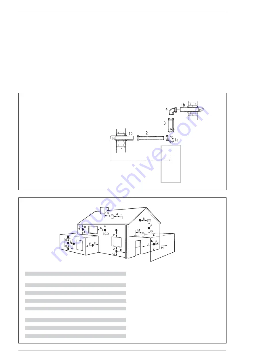
Fig. 8
Terminal position
Minimum spacing
A
Directly below an openable window, air vent
or any other ventilation opening
300 mm 12 in
B
Below guttering, drain pipes or soil pipes
75 mm
3 in
C/D
Below eaves, balconies or carport roof
200 mm
8 in
E
From vertical drain pipes or soil pipes
75 mm
3 in
F
From internal or external corners
300 mm 12 in
G
Above adjacent ground, roof or balcony level
300 mm 12 in
H
From a surface facing the terminal
600 mm 24 in
I
From a terminal facing the terminal
1,200 mm 48 in
J
From an opening in the carport
(eg door, window into dwelling)
1,200 mm 48 in
K
Vertically from a terminal on the same wall
1,500 mm 60 in
L
Horizontally from a terminal on the same wall
300 mm 12 in
M
Horizontally from a vertical terminal to a wall
300 mm 12 in
N
Horizontally from an openable window or other opening 300 mm 12 in
P
Above an openable window or other opening
300 mm 12 in
TABLE 1
Fig. 7
IMPORTANT:
Each additional 90° curve installed reduces
the available length by 0.90 metres.
Each additional 45° curve installed reduces
the available length by 0.45 metres.
max 4,6 m
KEY
1a-b Coaxial duct kit code 8096250
2a
Extension L. 1000 code 8096150
2b
Extension L. 500 code 8096151
3
Vertical extension L. 140 with take-off point code 8086950
4a
90° additional bend code 8095850
4b
45° additional bend code 8095950
NOTE: Before installing accessories, lubricate the internal part of
gaskets with silicon-based products. Avoid using oils and greases.
NOTE: Place the duct horizontally.
11


