24
0
30
20
10
∆
p aria mm H
2
O
P
o
tenza t
e
rmica kW
25
20
10
15
50
40
60
5
30
50-30
°
C
35
70
80-60
°
C
0
30
20
10
∆
p aria mm H
2
O
P
o
tenza t
e
rmica kW
25
20
10
15
50
40
60
5
30
50-30
°
C
35
70
80-60
°
C
G20
G31
4.3.1
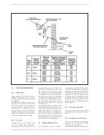
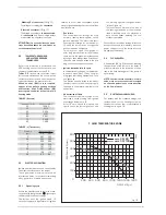
Diagram illustrating heat output in relation to “air
∆
p”
TABLE 4/a - G20
* Air
∆
p is measured during boiler operation using a differential pressure gauge connected to the ventilator intake.
** The gas consumptions refer to the calorific value at standard conditions at 15°C - 1013 mbar.
Variable heat output
Air
∆
p*
Gas consum.**
(80-60°C) (50-30°C)
(80-60°C) (50-30°C)
G20
kW
kW
mm H
2
O
mm H
2
O
m
3
/h st
29,3
32,0
63,8
66,4
3,17
22,9
25,0
45,0
45,0
2,48
16,1
17,6
25,0
25,0
1,75
10,4
11,4
8,4
9,2
1,14
TABLE 4/b - G31
Variable heat output
Air
∆
p*
Gas consum.**
(80-60°C) (50-30°C)
(80-60°C) (50-30°C)
G31
kW
kW
mm H
2
O
mm H
2
O
kg/h
29,3
32,0
68,4
70,4
1,52
21,8
23,4
45,0
45,0
1,19
15,4
16,6
25,0
25,0
0,84
10,4
11,4
9,2
9,5
0,55
Fig. 22
Heat out
out (kW)
Air
∆
p mm H
2
O
Heat out
out (kW)
∆
p de aire mm H
2
O
4.4
COMMISSIONING
The gas valve is factory set and should
require no adjustment.
PLEASE NOTE: The combustion for this
appliance has been checked, adjusted and
preset at the factory for operation on the
gas type specified on the appliance data
plate. However it is advisable to check for
correct combustion having first checked:
– That the boiler has been installed in
accordance with these instructions.
– The integrity of the flue system and the
flue seals
– The integrity of the boiler combustion cir-
cuit and the relevant seals.
Proceed to put the boiler into operation as
follows, after installation a gas purge and
tightness/drop test have been made.
Ensure that the pump has been manually
rotated. Switch the boiler to the SUMMER
position. Open the gas cock, Ensure that any
timers or room thermostats are in the on
position.
The boiler will attempt to light.
4.5
CHECK THE OPERATIONAL
(WORKING) GAS INLET PRESSURE
Set up the boiler to operate at maximum
rate condition (chimney sweep) as
described in 4.6.2.
With the boiler operating in the maximum
rate condition, check that the operational
(working) gas pressure at the inlet test
point (see fig. 20 item 3), complies with the
requirements of 1.3.
Ensure that this inlet pressure can be main-
tained with all other appliances in the prop-
erty working.
4.5.1
Combustion Check
Competence to carry out the check of the
combustion performance.
PLEASE NOTE: BS 6798: 2009 Specification
for installation and maintenance of gas-fired
boilers of rated input not exceeding 70 kw
net advises that:
– The person carrying out a combustion
measurement should have been
assessed as competent in the use of a
flue gas analyser and the interpretation
of the results;
– The flue gas analyser should be one
meeting the requirements of BS7927 or
BS-EN50379-3 and be calibrated in
accordance with the analyser manufac-
turers requirements, and competence
can be demonstrated by satisfactory
completion of the CPA1 ACS assessment
which covers the use of electronic
portable combustion gas analysers in
accordance with BS7967, parts 1 to 4.
Connect the flue gas analyser to the flue
gas sampling point as shown in fig 23 and
check the combustion following the
sequence described in 4.4.
CO / CO
2
RATIO
Fig. 23
CO ppm
1
00
400
CO
2
%
NG 9%
0,0011
0,0044
LPG 10%
0,0010
0,0040
Содержание Dewy 130 HE FS
Страница 3: ......
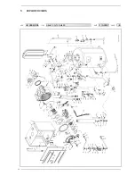
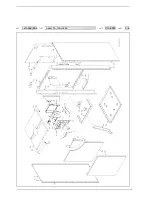
Страница 32: ...32 5 EXPLODED VIEWS COD TYPE DATE PAGE 3810009 505 DEWY 30 130 HE FS 31 10 2007 1 6 ...
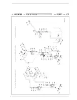
Страница 33: ...COD TYPE DATE PAGE 3810009 505 DEWY 30 130 HE FS 31 10 2007 2 6 33 ...
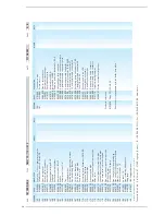
Страница 34: ...34 COD TYPE DATE PAGE 3810009 505 DEWY 30 130 HE FS 31 10 2007 3 6 ...
Страница 39: ......

