


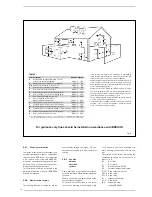


2.7
POSITIONING THE
OUTLET TERMINALS (fig. 9)
The outlet terminals for forced-draught
appliances may be located in the external
perimeter walls of the building.
To provide some indications of possible solu-
tions,
Table 4
gives the minimum distances
to be observed, with reference to the type
of building shown in fig. 9.
2.9
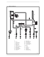
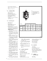
ELECTRICAL CONNECTION
The boiler is supplied with an electric cable.
Should this require replacement, it must be
replaced with one of similar type and dimen-
sions.
The electric power supply to the boiler must
be 230V - 50Hz single-phase through a 3 amp
fused main switch, with at least 3 mm spacing
between contacts.
Respect the L and N polarities and the earth
connection.
NOTE: SIME declines all responsibility for injury
or damage to persons, animals or property,
resulting from the failure to provide for proper
earthing of the appliance, or incorrect connec-
tion of external controls. Any fault or compo-
nent failure due to incorrect connection of
external controls is not covered in the warranty.
120
183
13
9
18
5
18
5
80
80
1
2
3
CS
CA
1
30 (ver
s. HE 35)
Fig. 7
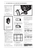
KEY
1
Adaptor with vent
2
Air intake
3
Exhaust
CA Inlet
CS Outlet
13
9
C
C33
11
10
3
1
1
3
3
7
3
12
12
12
Fig. 8
C13
3
2
3
1
14
12
13
12
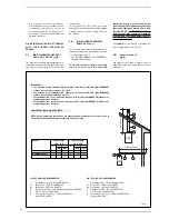
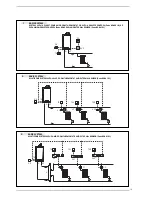
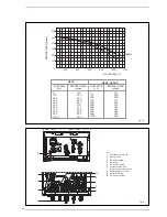
NOTE
Before connecting accessories, it is
always advisable to lubricate the inter-
nal part of the gaskets with silicon
products. Avoid using oils and grea-
ses.
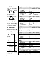
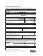
TABLE 3
MERIDIAN HE 30 C
Load loss - mm H2O
Inlet
Exhaust
1 Air/smoke divider, code 8093050
0
0
2 90° bend, code 8077450
0.25
0.30
3 a Extension 80mm L. 1000, code 8077351
0.20
0.20
3 b Extension 80mm L. 500, code 8077350
0.10
0.10
7 45° bend, code 8077451
0.20
0.20
9 Inlet/ exhaust fitting, code 8091401
--
--
10 Articulated tile, code 8091300
--
--
11 Vertical roof terminal, code 8091212B *
1.10
0.15
13 Inlet/ exhaust fitting, code 8091401
--
--
14 Coaxial Terminal, code 8096253A *
1.10
0.15
* This loss includes the losses with use of item 9 or 13


