Smart Machine Smart Decision
SIM868_Series_Hardware_Design_V1.06
44
2017-07-13
Module
GND
(Pin33)
RF connector
R101
GSM_ANT
C101
C102
GND
(Pin31)
GSM
Antenna
(Pin32)
D101
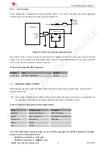
Figure 37: GSM antenna matching circuit
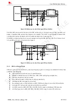
The RF connector is used for conduction test. If the space between RF pin and antenna is not enough, the
matching circuit should be designed as in the following figure:
Module
R101
GSM_ANT
C101
C102
GND
(Pin33)
GND
(Pin31)
GSM
Antenna
(Pin32)
D101
Figure 38: GSM antenna matching circuit without RF connector
In above figure, the components R101, C101 and C102 are used for antenna matching, the value of the
components can only be got after the antenna tuning, usually, they are provided by antenna vendor. By default, the
R101 is 0
Ω
resistor, and the C101, C102 are reserved for tuning.
The RF test connector in the figure is used for the conducted RF performance test, and should be placed close to
the module’s antenna pin. The traces impedance between components must be controlled in 50
Ω
.The component
D101 is a bidirectional TVS component, which is used for ESD protection, the recommended part numbers of the
TVS are listed in the Table 27:
Table 27: Recommended TVS component
Package
Type
Supplier
0201
LXES03AAA1-154
Murata
0402
LXES15AAA1-153
Murata
SIMCOM
CONFIDENTIAL
FILE


