background image

1.4  

ACCESSORIES PROVIDED

POKER PRO comes with a set of accessories for its operation and maintenance (tools, hex wrenches...) supplied 
in a special tool kit comprising:

stop bar 

fuses 4 Amp.- delayed

Allen keys set 1,5 ÷ 5 mm

ø 1,7 mm steel pin

13 mm spanner

19 mm spanner

ø 1,2 mm steel pin

slanted brush

laser warning label (Ch.1.2)

Quick Guide (Ch.3.4.3)

adhesive hooks for Quick Guide

  Cutter on machine:

 Separately:

cutter U01W

fi

 xing bracket: 

Operating manual

POKER PRO

Copyright Silca 2019

8

Содержание POKER PRO

Страница 1: ...EN Operating Manual Translation of original instructions D4A1214XA vers 1 0 POKER PRO...

Страница 2: ...ety This document or any of its parts cannot be copied altered or reproduced without written authorization from the Manufacturer Keep the manual and look after it for the entire life cycle of the mach...

Страница 3: ...1 3 4 2 Fixing bracket 11 3 4 3 Quick Guide 12 3 5 WORK STATION DESCRIPTION 12 4 CLAMPS 13 4 1 CLAMPS ROTATION 14 4 2 USE OF THE GAUGES 14 4 3 STOP POSITIONS KEY STOP 16 4 4 USE OF PINS 17 4 5 CUTTING...

Страница 4: ......

Страница 5: ...s ID Poker PRO has an ID plate located on the back of the machine showing the serial number Fig 1 see Ch 9 DISPOSAL How to apply for after sales service Silca provides purchasers of POKER PRO with Aft...

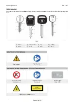
Страница 6: ...ead 2 Neck 3 Shoulder stop 4 Blade 5 Tip 6 Back 7 Cutting 8 Stem GRAPHICS IN THE MANUAL Pay attention Obligation to read the manual GRAPHICS ON THE POKER PRO KEY CUTTING MACHINE Do not clean with comp...

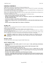
Страница 7: ...sonnel professional use The POKER PRO key cutting machine is designed for use on business or industrial premises e g hardware shops key cutting centers etc Any other use different from that indicated...

Страница 8: ...cut flat cylinder keys vehicle keys and cruciform keys Keys are read by an optical reader laser Keys are cut in a single operation The key blank is cut directly as the original key is being read POKER...

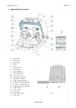
Страница 9: ...partment K Swarf collection tray M Clamp cutter side M1 Clamp knob cutter side N Key gauge cutter side P Clamp optical reader side P1 Clamp knob optical reader side Q Key gauge optical reader side R P...

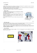
Страница 10: ...controlled shield deactivates operation and movement including that of the cutter A warning light indicates that the shield is not closed see Ch 6 To re activate the work cycle lower the shield and p...

Страница 11: ...roller guides Clamps rotating with four sides used to secure keys perfectly fitted either on their backs or profiles for keys with symmetrical cuts Runs asse X 30 mm asse Y 54 mm Dimensions width 318...

Страница 12: ...ial tool kit comprising stop bar fuses 4 Amp delayed Allen keys set 1 5 5 mm 1 7 mm steel pin 13 mm spanner 19 mm spanner 1 2 mm steel pin slanted brush laser warning label Ch 1 2 Quick Guide Ch 3 4 3...

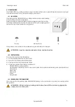
Страница 13: ...ATTENTION keep the complete packing for future machine transfers 2 2 UNPACKING To remove the machine from its packing 1 Cut the strapping with scissors and remove 2 Open the box carefully without dama...

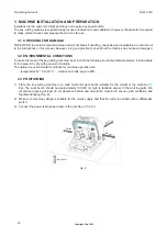
Страница 14: ...environmental parameters it is advisable for the area to be dry with good air circulation The optimum environmental conditions for machine operation are temperature 10 C to 40 C relative humidity app...

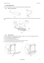
Страница 15: ...4 2 Fixing bracket If the key cutting machine is transported and used on a vehicle e g a van it must be prepared as follows 1 Turn off the machine and detach the power lead 2 Remove the tablet holder...

Страница 16: ...ing parts General ON OFF emergency button R located on the right hand side of the machine START button A STOP button B Safety shield C CUTTER F Clamp M for key blank CUTTER side OPTICAL READER H Clamp...

Страница 17: ...ition with the most suitable side for the key to be cut Side A for keys to be fitted on their backs keys with double cuts without groove and cruciform keys Side B for keys placed on their backs and ha...

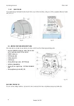
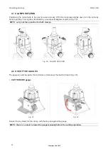
Страница 18: ...0 NOTE carry out the operation for both clamps Fig 20 CLAMPS ROTATION 4 2 USE OF THE GAUGES The gauge is used to position flat cylinder or vehicle keys that call for Stop 0 Fig 29 CUTTER SIDE gauge Fi...

Страница 19: ...MUST BE TAKEN MANUALLY TO ITS ORIGINAL POSITION Fig 28 For all reading and cutting operations the gauge I must be taken back manually to its original position Fig 28 in this position it covers the se...

Страница 20: ...th the tip as a reference The choice of position 1 or 2 depends on the length of the cuts Insert the bar into the grooves on the clamp ATTENTION remove the bar before proceeding with the cutting opera...

Страница 21: ...and therefore can be copied Fig 32 NOTE use pins with the same diameters for locking both the original and the key blank Fig 32 Fig 33 4 5 CUTTING CRUCIFORM KEYS The standard 4 sided clamp can be used...

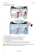
Страница 22: ...E 5 Take the reader side gauge to the original position Fig 28 page 15 6 Lower the safety shield C 7 Press START to start the cutting operation indicated by a BLUE LIGHT Fig 37 BLUE light 8 The end of...

Страница 23: ...D C B A D C B A Fig 37 BLUE light D C B A D C B A Fig 38 GREEN light Operating manual POKER PRO Copyright Silca 2019 19...

Страница 24: ...tter motor stalled Cutter locked on key Press STOP to re position the carriages Raise and lower the shield and press START to re position the carriages and re start the cycle Contact Silca After Sales...

Страница 25: ...ns Under no circumstances should compressed air be used to clear the work zone of chippings as this will blow them onto the moving parts Never use oily products or thinners for cleaning painted surfac...

Страница 26: ...ct with the electronic parts Before performing any type of maintenance checks or replacements read the warnings below Do not perform any maintenance operations with the machine on Always disconnect th...

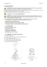
Страница 27: ...Fig 42 ATTENTION THE THREAD IS LEFT HANDED 5 Remove the nut F2 hex washer F1 and cutter F Fig 43 6 Carefully clean the cutter shaft seat and the new cutter 7 Fit the new cutter F paying attention to t...

Страница 28: ...e in good condition even when they are electrically faulty Fuses must always be replaced with the same amperage and type rapid or delayed as indicated in this manual POKER PRO has 1 fuse 4 Amps delaye...

Страница 29: ...ve the screws E2 and washers E3 Fig 48 5 Remove the top cover E 6 Place the new cover in position paying attention to the keypad flat cable 7 Connect the keypad flat cable to the circuit board 8 Secur...

Страница 30: ...t the end of its useful life and replace it with an equivalent product designed for the same use In this latter case the user may ask the manufacturer to collect the existing equipment c by the manufa...

Страница 31: ...anual there is a list of manufacturers and authorized Service Centre addresses if the manual was downloaded is necessary visit the website to see the contacts www silca biz 10 1 HOW TO REQUEST SERVICE...

Страница 32: ...Operating manual POKER PRO Copyright Silca 2019 28...

Страница 33: ...J10 gauge sensor J13 X axis motor J12 X axis sensor J15 Y axis sensor J14 Y axis motor micro carter J7 cutter motor J4 power supply 24V J20 not used J23 white led J9 optic reader J22 micro carter Ope...

Страница 34: ...ARD J14 STEP MOTOR Y AXIS STEP MOTOR X AXIS red light blue green yellow red white red green white green MOTHER BOARD J12 X AXIS SENSOR Y AXIS SENSOR MOTHER BOARD J15 yellow black light blue brown blac...

Страница 35: ...ICRO CARTER MOTHER BOARD J8 MOTHER BOARD J23 black orange white green brown blue grey red WHITE LED LAMP 3 COLORS LED LAMP RED LIGHT GREEN LIGHT BLUE LIGHT 1 2 3 4 5 6 Operating manual POKER PRO Copyr...

Страница 36: ...blue black brown light blue CUTTER MOTOR MICRO CARTER M Cutter motor Micro carter POWER SUPPLY 24V 24V 1 6 1 2 3 red 4 black 5 black 6 black 1 2 red red black black MOTHER BOARD J4 MOTHER BOARD J7 Op...

Страница 37: ...calibre Detector calibre Sensor calibre Gauge sensor J12 X axis sensor Sensore asse X Fuhler X Achse Senseur axe X Detector eje X Sensor eixo X X as sensor J13 X axis motor Motore asse X Motor X Achse...

Страница 38: ...n DIRECTIVE 2014 30 EU Electromagnetic Compatibility European Union DIRECTIVE 2014 35 EU Low Voltage European Union DIRECTIVE 2011 65 EU RoHS2 European Union DIRECTIVE 2012 19 EU WEEE 19 and with the...

Отзывы: