background image

USE

The key-cutting machine must be installed and used in the way laid down by the manufacturer in the Operating Manual.
If the key-cutting machine is used differently or for purposes different from those described in this manual, the customer will 
forego any rights he may have over the manufacturer. Furthermore, unforeseen danger to the operator or any third parties may 
arise from incorrect use of the machine. 
Negligence in the use of the machine or failure on the part of the operator to observe the instructions given in the manual are 
not covered by the guarantee and the manufacturer declines all responsibility in such cases. 

Further risks

There are no further risks arising from the use of the machine.

Protection and safety precautions for the operator 

Our key-cutting machines are designed with features which make it completely safe in all its parts and are built entirely to the 
Machine Directives.
The operations for which it has been designed are easily carried out at no risk to the operator.
Observation of safety regulations and the instructions provided by the manufacturer in this leaflet and the Operating Manual 
eliminate all human errors, unless deliberate.

MACHINE CHARACTERISTICS

Noise level

Power supply

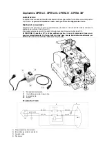
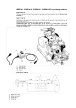
The machine is supplied with electricity by means of a separable earthed plug. 
The key-cutting machine must be connected to a socket provided with a differential switch.

Start-up

The machine is started up by means of the master switch.

Machine Identification

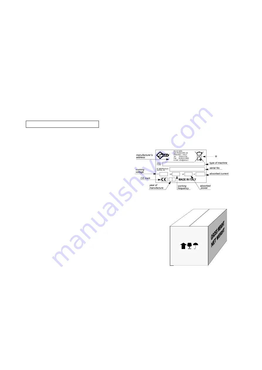
The key-cutting machine is provided with an identification label 
which shows the serial number. 

Use the serial number when ordering spare parts 
or requesting servicing.

(*) see "DISPOSAL".

TRANSPORT

Our key-cutting machines are easily transported by one or 
more persons (if the weight is over 25-30 Kg.) and is not dangerous to handle. 

Packing

Internally the packing comprises expanded polymer shells which enclose the 
machine and its parts, holding them securely in place during handling.
A robust cardboard box and nylon wrapping give further protection to the machine 
even for long storage periods.

Transport

The packing protects the machine from the risks of handling (knocks, etc.) and is 
clearly marked with suitable symbols showing the ideal conditions for transport.

Contents of packing

Check that the packing box contains:
1 key-cutting machine enclosed in the protective shells
1 supply connecting wire
1 tool kit
1 set of documents, including:  
       Operating Manual, General Instructions, Spare parts list, Guarantee form
It is advisable to keep the cardboard box in good condition, as it may be used again (e.g. removals, dispatch to the manufactur-
ers for repairs or servicing).

Handling the machine

When the key-cutting machine has been unpacked, place it directly on its workbench. This operation can be carried out by one 
or more persons 

firmly holding the base, and no other part, to lift and carry the machine.

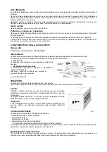
Noise pressure:  Lp (A) =  84,69 dB (A)

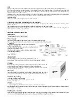
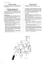
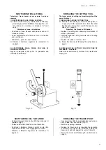
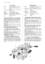
Fig. 1

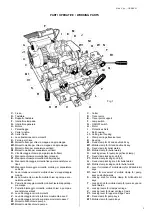
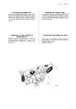
Fig. 2

Содержание OPERA IV

Страница 1: ...Operating manual D408570XA vers 2 0...

Страница 2: ......

Страница 3: ...l interruttore X1 Si accende la lampada spia X2 quando indica la presenza di tensione nella spina X3 ATTENZIONE l interuttore X1 di tipo elettromagnetico in caso di mancanza di tensione si spegne auto...

Страница 4: ...sing the switch X1 The warning light X2 illuminates to indicate voltage in the plug X3 ATTENTION Switch X1 is electromagnetic in the event of a power failure it goes out automatically When electricity...

Страница 5: ...e mai violentemente il cavo di alimentazione elettrica ed assicurarsi che non venga a contatto con olio oggetti taglienti o calore Non rimuovere mai dalla spina la messa a terra Assicurarsi che il cav...

Страница 6: ...e della macchina avviene azionando l interruttore generale Identificazione della macchina La duplicatrice provvista di targhetta di identificazione contenente la matricola Utilizzare il numero di matr...

Страница 7: ...ra nuova equivalente ed adibita alle stesse funzioni b dal produttore inteso come il soggetto che ha per primo introdotto e commercializzato in Italia o rivende in Italia col proprio marchio l apparec...

Страница 8: ......

Страница 9: ...he cutting tool or brush if applicable 6 Never tug at the electricity supply wire and make sure it does not come into contact with oil sharp objects or excessive heat Never remove the earth wire from...

Страница 10: ...provided with a differential switch Start up The machine is started up by means of the master switch Machine Identification The key cutting machine is provided with an identification label which shows...

Страница 11: ...y the user when the equipment was placed on the market before 31 December 2010 and the user personally decides to eliminate it without replacing it with new equivalent equipment designed for the same...

Страница 12: ......
Страница 13: ...fresa su diversi materiali velocit 1 acciaio velocit 2 ottone Lampada orientabile di serie OPERA IV Professional key cutting machine for mortice and bit keys double bit keys pin and pipe keys and keys...

Страница 14: ...ipers g Chiave fissa 17 mm 17 mm spanner b Serie chiavi esagonali 6 pz Set of Allen keys 6 pcs f Chiave fissa 10 mm 10 mm spanner a Set scatola corredo Tool box 1 Testa 5 Fermo 1 Head 5 Shoulder 2 Gam...

Страница 15: ...o inferiore movimento asse X V1 Leva bloccaggio carrello superiore movimento asse Y W Morsetto fisso chiavi a pompa W1 Morsetto mobile chiavi a pompa PARTI OPERATIVE WORKING PARTS F G H C V1 M1 S R K...

Страница 16: ...l riferimento Y Fig 2 sulla base della macchina 1 riferimento per cifrare chiavi a mappa doppia mappa 2 per chiavi a pompa 3 per scanalature verti cali TECHNICAL DATA Motor twin speed 1355 660 rpm sin...

Страница 17: ...edi pag 2 FITTING LEVERS R AND R1 Screw the lever in almost all the way to the ideal position Fig 3b Tighten nut Z using the spanner provided g see page 2 MONTAGGIO DELLA LEVA L Inserire la leva L nel...

Страница 18: ...uato Per fare questo tenere fermo con una mano la parte zigrinata del volantino E3 e con l altra girare la parte mobile del volantino E4 M1 S X X P P1 M E2 E4 E3 R Fig 6 SETTING SPACING The spacing on...

Страница 19: ...onare il carrello porta morsetti allineando il riferimento Y con il 1 riferi mento del carrello vedi freccia Fig 7 Ribloccare poi le levette U MICROMETRIC TRACER POINT A micrometric tracer point on a...

Страница 20: ...alla cifratura della chiave B abbassando lentamente la leva R Spostare il carro con la leva di traslazione L e continuare con le altre cifrature della chiave ripetendo l operazione sopra descritta Pl...

Страница 21: ...nt of the original key CIFRATURA DI CHIAVI A POMPA Sbloccare le levette U e posizionare il carrello porta morsetti allineando il riferimento Y con il 2 riferimento del carrello vedi freccia Fig 8 Ribl...

Страница 22: ...ith the tracer point ESECUZIONE SCANALATURE VERTICALI Sbloccare le levette U e posizionare il carrello porta morsetti allineando il riferimento Y con il 3 riferimento del carrello vedi freccia Fig 9 R...

Страница 23: ...hten the screw E5 holding the tracer point right up against the end of its seat Re set the tracer point following the instructions on page 6 SOSTITUZIONE DELLA FRESA Tastatore e fresa devono avere sem...

Страница 24: ...riserva il diritto qualora lo ritenga necessario di poter variare in qualsiasi momento forme particolari e materiali della macchina stessa senza alcun preavviso SPARE PARTS We recommend the use of or...

Страница 25: ...uzione fresa pag 11 Sostituzione tastatore pag 11 Ricambi pag 12 Manutenzione pag 12 Garanzia pag 12 INDEX Accessories provided page 2 Working parts page 3 Technical data page 4 Preliminary operations...

Страница 26: ...lati nelle seguenti Direttive Europee DIRETTIVA 2006 42 CE Macchine delle Comunita Europee E alle Norme EN 292 1 EN 292 2 DIRETTIVA 2004 108 CE Compatibilita Elettromagnetica delle Comunita Europee E...

Страница 27: ...an Directives European Union DIRECTIVE 2006 42 CEE Machines and with the EN 292 1 EN 292 2 Standards European Union DIRECTIVE 2004 108 CE Electromagnetic Compatibility and with the EN 55013 section 3...

Страница 28: ...SILCA S p A Via Podgora 20 Z I 31029 VITTORIO VENETO TV Tel 0438 9136 Fax 0438 913800 E mail silca silca it www silca biz Members of the Kaba Group...

Отзывы: