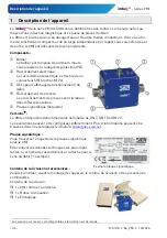
IMPORTANT! Shielding required!
Use only shielded connection cables.
The shield of the connection cable should not be
connected to earth.
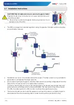
We recommend to earth the pipes directly before and
behind the VMI (
Figure).
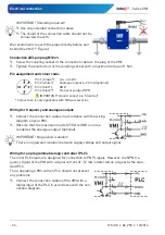
Connection 4(5)-pin plug M12x1:
Screw the coupling socket of the connection cable to the plug of the VMI.
Tighten the knurled nut of the coupling socket with a maximum torque of 1 Nm.
Pin assignment and colour code:
Pin 1 (brown*): +U
B
= 24 V
DC
Pin 2 (white*):
Analogue output 4…20 mA (optional)
Pin 3 (blue*):
GND
Pin 4 (black*):
Frequency output NPN
IMPORTANT! Do not connect pin 5 (centre)!
* Colour code is only applicable with SIKA accessories.
Wiring for frequency and analogue output:
Connect the connection cables in accordance with the wiring
diagram on your VMI.
Observe that the maximum load of 250
Ω
to GND is not ex-
ceeded at the analogue output (optional).
IMPORTANT! No galvanic isolation!
There is no galvanic isolation between supply voltage and output signal.
Wiring for an programmable logic controller (PLC):
The most PLC inputs are designed for connection to PNP signals. However, the NPN fre-
quency signal of the VMI with a signal current of ~12 mA is detected as a signal by the stan-
dard PLC.
Thus, operating a VMI with an PLC should not present
any problems.
Connect the connection cables of the VMI with a
digital input of the PLC in accordance with the con-
nection diagram.

