background image

Installation of VMI


i

ndu

Q

®

 - Series VMI  

- 24 - 


© SIKA  •  Ba_VMI  •  10/2014 

4.1


Installation instructions 


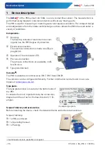
CAUTION! Risk of malfunction due to external magnetic fields! 

Magnetic fields close to the device can cause malfunctions and 

should be avoided. 


 Ensure that no external magnetic fields are present at the in-

stallation site of the VMI. 


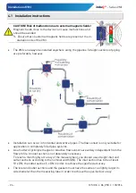
The VMI can always be installed anywhere along the pipeline. Straight sections of piping 
are preferable, however. 


Installation can occur in horizontal and vertical pipes. The flow sensor is only suitable for 

application in completely filled pipe systems. 


As a matter of principle magnetic inductive flow sensors are widely independent from the 

flow profile. An inlet section is not absolutely necessary. 

To reach a most highly accuracy of the measurement, you should use straight inlet and 

outlet sections according to the nominal width (DN). The inlet section has to be at least 

10 x DN; the outlet section 5 x DN in order to achieve the specified accuracy. 


The inlet and outlet sections and the gaskets must have the same or a slightly larger in-
side diameter than the measuring tube in order to achieve the specified accuracy. 


Содержание INDUQ VMI 07

Страница 1: ...en Sie diese Betriebsanleitung bei der Ver u erung des Ger tes mit SIKA Ba_VMI 10 2014 Magnetisch induktiver Durchflusssensor induQ Baureihe VMI Betriebsanleitung Original Betriebsanleitung Seite 1 16...

Страница 2: ...Ausschalten 11 6 3 Messbetrieb 11 7 Wartung und Reinigung 12 8 Demontage und Entsorgung 12 9 Technische Daten 13 9 1 Kenndaten VMI 13 9 2 Werkstofftabelle 14 9 3 Druckverlust 14 9 4 Abmessungen 15 ind...

Страница 3: ...hr Dieses Zeichen kennzeichnet Gefahren die Personensch den verursachen die zu gesund heitlichen Sch den f hren oder erheblichen Sachschaden verursachen k nnen VORSICHT Elektrischer Strom Dieses Zeich...

Страница 4: ...5 Pin Stecker M12x1 LED f r Betriebs Durchflussanzeige Prozessanschluss Die Prozessanschl sse sind in ver schiedenen Gr en lieferbar Typenschild Aufkleber Ausf hrungen Der VMI ist in den Nenngr en DN...

Страница 5: ...tet Die angegebenen Grenzwerte 9 Technische Daten d rfen keinesfalls berschritten werden berpr fen Sie vor dem Einbau ob die benetzten Werkstoffe des Ger tes f r die verwendete Fl ssigkeit geeignet si...

Страница 6: ...fweisen Dies kann durch Schulung oder entsprechende Unterweisung geschehen Dem Personal muss der Inhalt der vorliegenden Betriebsanleitung bekannt und jederzeit zug nglich sein Der elektrische Anschlu...

Страница 7: ...ng eines Leiters in einem Magnetfeld wird eine Gleichspannung erzeugt Beim VMI befindet sich das Messrohr in einem Magnet feld B Eine elektrisch leitf hige Fl ssigkeit Q flie t durch das Messrohr Dabe...

Страница 8: ...rleitungen erfolgen Der Durchflusssensor ist ausschlie lich f r den Einsatz in komplett gef llten Leitungen geeignet Prinzipbedingt sind magnetisch induktive Durchflusssensoren weitgehend unabh ngig v...

Страница 9: ...rauben Sie die berwurfmuttern der Anschlussver schraubung auf die Prozessanschl sse des VMI VORSICHT Materialschaden Beim Anziehen der berwurfmuttern am Sechskant des Pro zessanschlusses gegenhalten O...

Страница 10: ...itte darf nicht beschaltet werden Farbcode nur bei SIKA Zubeh r g ltig Beschaltung bei Frequenz und Analogausgang Verbinden Sie die Anschlussleitungen entsprechend dem An schlussbild auf ihrem VMI Bea...

Страница 11: ...esssystem durch Sp len entl ftet ist 6 2 Ein und Ausschalten Der VMI hat keinen Schalter und kann nicht eigenst ndig ein oder ausgeschaltet werden Das Ein und Ausschalten erfolgt ber die angeschlossen...

Страница 12: ...Gegenst nde oder aggressive Reinigungsmittel beim Reini gen 8 Demontage und Entsorgung VORSICHT Verletzungsgefahr Entfernen Sie niemals das Ger t aus einer im Betrieb befindlichen Anlage Sorgen Sie d...

Страница 13: ...Frequenzausgang Pulsrate optional 2 855 Pulse l 1 2000 Pulse l 855 Pulse l 1 1000 Pulse l 200 Pulse l 1 200 Pulse l Aufl sung optional 2 1 2 ml Puls 1000 0 5 ml Puls 1 2 ml Puls 1000 1 ml Puls 5 ml P...

Страница 14: ...atur 5 90 C Umgebungstemperatur 5 70 C Nennweite DN 7 DN 10 DN 20 Nenndruck PN 16 Prozessanschluss G ISO 228 au en G ISO 228 au en G1 ISO 228 au en 9 2 Werkstofftabelle Bauteil Werkstoff Bauteil benet...

Страница 15: ...induQ Baureihe VMI Technische Daten Technische nderungen vorbehalten 15 9 4 Abmessungen VMI 07 und VMI 10 VMI 20...

Страница 16: ...a_VMI 10 2014 Mechanische Messtechnik Durchflussmesstechnik Elektronische Mess Kalibriertechnik SIKA Dr Siebert K hn GmbH Co KG Struthweg 7 9 D 34260 Kaufungen Germany 49 0 5605 803 0 49 0 5605 803 54...

Страница 17: ...the device is resold please provide the operating manual along with it SIKA Ba_VMI 10 2014 Magnetic inductive flow sensor induQ Series VMI Operating manual Translation Betriebsanleitung Seite 1 16 Op...

Страница 18: ...on and off 27 6 3 Measuring mode 27 7 Maintenance and cleaning 28 8 Disassembly and disposal 28 9 Technical data 29 9 1 Characteristics VMI 29 9 2 Materials table 30 9 3 Pressure drop 30 9 4 Dimensio...

Страница 19: ...CAUTION Risk of injury This sign indicates dangers that cause personal injuries that can lead to health defects or cause considerable damage to property CAUTION Electric current This sign indicates d...

Страница 20: ...al connection is made via 4 5 pin plug M12x1 Operation flow indicator LED Process connection The process connections are available in dif ferent sizes Type plate sticker Versions The VMI is available...

Страница 21: ...r no circumstances be exceeded Before installing the device check that the wetted materials of the device are compatible with the media being used 9 2 Materials table Measuring tube empty or partially...

Страница 22: ...of the VMI must hold a relevant qualification This can be based on training or relevant tuition The personnel must be aware of this operating manual and have access to it at all times The electrical c...

Страница 23: ...es in accordance with the principle of induction i e a DC voltage is generated by the movement of a conductor in a magnetic field The measuring tube of the VMI is located in a magnetic field B An elec...

Страница 24: ...and vertical pipes The flow sensor is only suitable for application in completely filled pipe systems As a matter of principle magnetic inductive flow sensors are widely independent from the flow prof...

Страница 25: ...I together with the gaskets Screw the union nuts of the screwed connection onto the process connections of the VMI CAUTION Material damage While tightening counter the union nut on the hexagon of the...

Страница 26: ...not connect pin 5 centre Colour code is only applicable with SIKA accessories Wiring for frequency and analogue output Connect the connection cables in accordance with the wiring diagram on your VMI O...

Страница 27: ...ly the measuring system is vented by flushing 6 2 Switching on and off The VMI has no switch and can therefore not be switched on and off independently Switching on and off takes place via the connect...

Страница 28: ...use sharp objects or aggres sive agents for cleaning 8 Disassembly and disposal CAUTION Risk of injury Never remove the device from a plant in operation Make sure that the plant is shut down professio...

Страница 29: ...nal 2 855 pulses l 1 2000 pulses l 855 pulses l 1 1000 pulses l 200 pulses l 1 200 pulses l Resolution optional 2 1 2 ml pulse 1000 0 5 ml pulse 1 2 ml pulse 1000 1 ml pulse 5 ml pulse 1000 5 ml pulse...

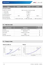
Страница 30: ...temperature 5 70 C Nominal diameter DN 7 DN 10 DN 20 Nominal pressure PN 16 Process connection BSP male thread BSP male thread 1 BSP male thread 9 2 Materials table Component Material Wetted componen...

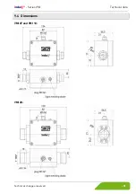
Страница 31: ...induQ Series VMI Technical data Technical changes reserved 31 9 4 Dimensions VMI 07 and VMI 10 VMI 20...

Страница 32: ...4 Mechanical measuring instruments Flow measuring instruments Electronic measuring calibration instruments SIKA Dr Siebert K hn GmbH Co KG Struthweg 7 9 D 34260 Kaufungen Germany 49 0 5605 803 0 49 0...

Страница 33: ...rter Joignez cette notice d utilisation la vente de l appareil SIKA Ba_VMI 10 2014 D bitm tre induction magn tique induQ S ries VMI Notice d utilisation Traduction Betriebsanleitung Seite 1 16 Operati...

Страница 34: ...et nettoyage 44 8 D montage et limination 44 9 Donn es techniques 45 9 1 Caract ristiques VMI 45 9 2 Tableau des mat riaux 46 9 3 Pertes de charge 46 9 4 Dimensions 47 induQ est une marque d pos e de...

Страница 35: ...e blessure Ce signe indique un danger susceptible d entra ner des blessures corporelles des domma ges personnels ou des d g ts mat riels consid rables ATTENTION Courant lectrique Ce symbole indique de...

Страница 36: ...nctionnement du d bit Raccordement de process Les raccordements de process sont livrables dans diff rentes tailles Plaque signal tique tiquette Versions Le VMI est disponible dans dimensions nominales...

Страница 37: ...s en vigueur Les donn es limites indiqu es 9 Donn es techniques ne doivent en aucun cas tre d pass es Veuillez contr ler avant le montage si les mat riaux impr gn s de l appareil sont adapt s pour le...

Страница 38: ...ou continue correspondante Le contenu de cette pr sente notice d utilisation doit tre connu du personnel et lui tre accessible tout moment Seul un lectricien est autoris effectuer le branchement lect...

Страница 39: ...e selon le principe de l induction c est dire qu une tension continue est g n r e par le mouvement d un conducteur dans un champ ma gn tique Dans le VMI le tube de mesure se trouve dans un champ magn...

Страница 40: ...es que verticales Le d bitm tre est exclusivement adapt une utilisation sur des canalisations compl te ment remplies Par principe les capteurs de d bit induction magn tique sont largement ind pendants...

Страница 41: ...eu de montage Placez l ensemble VMI avec les joints Vissez les crous d accouplement du raccordement sur du VMI ATTENTION D g ts mat riels Exercer un contre maintien lors du serrage de l crou raccord a...

Страница 42: ...e NPN IMPORTANT Broche 5 milieu ne doit pas tre connect e code couleur uniquement valable pour les accessoires SIKA Circuiterie pour la sortie de fr quence et la sortie analogique Reliez les c bles de...

Страница 43: ...de l art le syst me de mesure est d sa r par rin age 6 2 Mise en et hors Le VMI n a pas d interrupteur lui permettant d tre mis en ou hors circuit La mise en et hors circuit s effectuent par la tensi...

Страница 44: ...ntus ou de produits de nettoyage agressifs pour proc der au nettoyage 8 D montage et limination ATTENTION Risque de blessure N enlevez jamais l appareil d une installation en service Assurez vous que...

Страница 45: ...ulsions en option 2 855 impulsions l 1 2000 impulsions l 855 impulsions l 1 1000 impulsions l 200 impulsions l 1 200 impulsions l R solution en option 2 1 2 ml impulsion 1000 0 5 ml impulsion 1 2 ml i...

Страница 46: ...iante 5 70 C Diam tre nominal DN 7 DN 10 DN 20 Pression nominale PN 16 Raccord de processus G ISO 228 ext rieur G ISO 228 ext rieur G1 ISO 228 ext rieur 9 2 Tableau des mat riaux Pi ce Mat riau Pi ce...

Страница 47: ...induQ S ries VMI Donn es techniques Sous r serve de modifications techniques 47 9 4 Dimensions VMI 07 et VMI 10 VMI 20...

Страница 48: ...technik Flow measuring instruments Instruments de mesure de d bit Elektronische Mess Kalibriertechnik Electronic measuring calibration instruments Appareillages lectroniques de mesure et mat riels de...

Отзывы: