background image


- 18 - 

Boiler overheating temperature [A 99] - value, exceeding which causes 
permanent turn off of the fan to prevent boiler overheating. After the 
temperature increases above 80

˚

C the central heating pump is turned on to cool 

down the boiler. Overheating mode is shown by indicating error [E  2] on the 
display. It can be turned off by pressing STOP button, but only when 
temperature decreases below this temperature. 
Fan turn off also occurs in case of damage of the boiler temperature sensor 
which is shown on the display with error [E  1]. 

STB

 - the controller has additional protection against overheating which is 

independent from the processor. In case the temperature increases over 95°C, 
the control process is turned off by turning the fan off and launching the central 
heating pump. The fan and the pump are turned on to the control process again 
when temperature drops below 89°C.  
STB circuit enables more precise boiler work control and reduces overheating 
possibility. 
 

(6) No 

fuel 

No-fuel testing time during fuel firing start [Fd60] - after switching to WORK 
mode, if water temperature does not increase by 5°C in programmed time, the 
control process will be turned off and the display will show the message: 
[FUEL]. 
You can return to previous mode by pressing STOP button. No fuel testing time 
during fuel firing is finished after the set temperature is achieved. 
No-fuel testing time during work mode [Fb30] - in WORK mode, if temperature 
of water in the boiler decreases below temperature set with the thermostat, by 
hysteresis value, and does not increase by 5°C in the programmed time, the 
control process  will be turned off and the display will show the message: 
[FUEL]. 
You can cancel the alarm by pressing STOP button. 
 

(7) Additional 

output 

Additional output [Ar 0] – the controller has been equipped with an output that 
allows connection of the UM module. When the Ar parameter has the UM 
module value “0” it may control the oil or gas boiler – if such boiler exists in the 
heating circuit. After switching the controller with the main power switch the 
additional boiler is turned off and it turns on again when there is no fuel in the 
solid fuel boiler. This function is useful in heating systems where there is a solid 
fuel boiler used to cut the heating costs. After erasing the “no fuel” alarm by 
pressing STOP button the additional boiler is again turned off and the controller 
works again. Setting parameter [Ar] to “1” allows controlling the additional alarm 
signaling system with the UM module – which occurs on the controller. 
When Ar parameter is set to “2” the UM module allows controlling the mixing 
valve servo-motor in the central heating circuit depending on the room 
thermostat input. In this case the work of central heating pump depends only on 
the boiler temperature. 
 

Содержание Holzgas

Страница 1: ... Strasse 29 37 13599 Berlin Tel 49 30 30 64 17 29 Fax 49 30 30 64 17 27 info cht heizkessel de service cht heizkessel de w ww ww w c ch ht t h he ei iz zk ke es ss se el l d de e I IH HR R P PA AR RT TN NE ER R F FÜ ÜR R U UM MW WE EL LT TF FR RE EU UN ND DL LI IC CH HE ES S H HE EI IZ ZE EN N ...

Страница 2: ...on book of boiler Table of contents 1 Short description 3 2 Technical data 4 3 Fuel 8 4 Using and Service 8 5 Control 11 6 System 14 7 Parts 17 8 Boiler installation systems 19 www cichewicz com With us heating makes economies ...

Страница 3: ... in the working on the solid fuel with series of thermo chemical reactions the flammable gas becomes in the result of them Gasifing just defines oneself this cycle of conversions This process holds in the device called gas generator The type matter of the wood gas can look as follows oxide of the carbon of CO 19 hydrogen H2 18 methane CH4 1 25 dioxide of the carbon 12 steam water H2O 2 50 nitrogen...

Страница 4: ...stallations which computational temperature of supply do not cross 85 C They can be used in c h installations of flat council or productive buildings which users require automatic feeding of fuel Boilers can be assembled both in modern and conventional heating installations Boiler steering has the possibility of pump regulation also loading storage tank Boiler of type Westfalia Holzgas utilizes wo...

Страница 5: ...1 Technical data Power supply 230V 50Hz Temp of surroundings 0 40 C Power consumption 82W Temp of fumes do 350 C Expense of air 38 UM 11 Loudness 65dB Number of gears 1 Class of tightness IP44 Rotational speed 2400obr min Class of isolation F Condenser of the engine 3µF 450V Mass 2 2kg Kind of the work continuous Supply wire 0 6m External dimensions 186x174x174mm lg x wid x h 2 1 2 Wiring diagram ...

Страница 6: ...convective channels making the surface of heat exchange The combustion space is partly tiled with fire clay which attends as catalyst of combustion process The body of boiler is made from certified steels and welded in cover of argon Westfalia Holzgas is equipped in ceramic burner nozzle and ceramic deflectors 2 3 Special features of Sigma Holzgas Low exploitation cost Easy and simple service Long...

Страница 7: ... 7 2 4 Dimensions of Sigma Holzgas mm Sigma 20 Sigma 30 Sigma 50 A 1510 1510 1510 B 725 825 825 C 840 840 960 D 1030 1030 1150 a 1 1 2 b 1 1 2 c d ø160 ø160 Ø200 2 5 Schema of Westfalia Holzgas ...

Страница 8: ...0 15 50 4 3 Oak 3600 15 10 4 2 Beech 3450 14 40 4 0 4 Using and Service 4 1 Assembly 1 Fit the ceramic burner nozzle to the boiler via the rectangular hole located inside of boiler 2 Mount the ceramic deflectors into their place inside the lower chamber 1 2 4 2 Burning Put wood chips or sawdust as base then put inside little pieces of wood At the top put chunks of wood and set the fire with half o...

Страница 9: ...led down completely it is ready for cleaning Take the burner nozzle of the assembly hole remove the deflectors from the lower chamber The parts can now be worked with for cleaning To ensure best boiler operation cleaning should be done frequently This guarantees the best fuel efficiency The better the boiler is set up the longer the intervals between cleaning Shutter position Power Burning time in...

Страница 10: ...he tight rope Take out the ceramic nozzle Remove the ceramic deflectors from the lower chamber Brush them gently with soft brush Vacuum the left ash do not touch the ceramic elements with vacuum head 4 4 2 clearing the boiler The boiler should be emptied from ash and all of the surfaces should be brushed in order to remove soot particles ...

Страница 11: ...pipe does NOT clean itself You must do this yourself An old vacuum cleaner is the best method 4 4 3 Clearing the exchanger Upper cleanout Lower cleanout 4 4 4 Starting up after cleaning Reassemble the burner nozzle and fit deflectors into boiler Load the boiler partly and light it normally ...

Страница 12: ...id fuel fired boilers The temperature of the boiler is kept on level set by the user by controlling the speed of the blow in fan The controller constantly monitors the temperature of water in the boiler shows it on the display and controls the central heating pump To enable more precise temperature control of heated rooms the controller has been equipped with an input for room thermostat connectio...

Страница 13: ...hey are working properly The controller when power appears returns to its last state before turning off or power loss Front panel of the controller Pic 1 consists of 1 Master switch 2 Display indicating boiler temperature and parameters 3 Room thermostat indicator 4 Boiler thermostat knob 5 Central heating pump work indicator 6 STOP choose parameters erase alarms button 7 START choose parameters b...

Страница 14: ... of the parameter flashing Change of the parameter is done by pressing or buttons You can confirm new settings by pressing OK button and after that the controller allows choosing another parameter with buttons If you do not want to change the parameter value with the or button choose End and press OK or wait for 1 minute the controller will exit the user mode and will indicate the temperature of t...

Страница 15: ...t from user mode choosing the End on the display and pressing OK button causes exit from the parameter setting Exit from this mode will also occur if no button is pressed for 1 minute 6 2 5 Parameter setting the service mode Holding OK button for more than 3 seconds enters the service mode where you can review and change the parameters It is indicated by slow flashing of the room thermostat indica...

Страница 16: ... testing press OK launch boiler outr out3 outu Hot water pump output testing press OK launch outr out4 End Exit the service mode after pressing OK In the table above the first column represents example display indications in the next columns there are parameter description minimum and maximum values allowed to set step of the parameter during the setup The last column shows factory defaults to whi...

Страница 17: ...g to control the hot water tank loading pump by the UM UM 1 module The hot water temperature u50 temperature value which will be kept in the hot water tank The heating hysteresis of the hot water heating uh5 value which the temperature in the tank has to decrease by so that the hot water pump turns on in order to heat up the water in the tank Parameter ur 1 the ur 0 value indicates no sensor or ho...

Страница 18: ...g time during fuel firing is finished after the set temperature is achieved No fuel testing time during work mode Fb30 in WORK mode if temperature of water in the boiler decreases below temperature set with the thermostat by hysteresis value and does not increase by 5 C in the programmed time the control process will be turned off and the display will show the message FUEL You can cancel the alarm...

Страница 19: ...er also exits service mode when no buttons are pressed for 1 minute 6 2 6 Additional functions To improve comfort in heated rooms the controller has been equipped with an input that allows connecting any kind of room thermostat with contact output When temperature in the room is below desired temperature the central heating pump is turned on and the room thermostat indicator is lit It means that t...

Страница 20: ...he display after erasing it by pressing STOP button in spite of temperature decreasing below 90 C may mean permanent damage of boiler temperature sensor e g if the boiler has been overheated above 150 C In case of programming the sensor and central heating pump in the service mode the controller tests the hot water sensor circuit Appearing of fault E8 means damage or lack of hot water sensor Pictu...

Страница 21: ...oiler overheating protection 90 99 C 1 C Hardware boiler overheating protection STB 95 C 1 C Central heating pump launch temperature 30 70 C 1 C Hot water temperature adjusting range 30 60 C 1 C Total fan out total max 2A 230V Dimensions HxWxD 80x170x100 mm 6 2 10 Notes Display Parameter User 100 Fan max work power or max power when r 0 10 r 1 automatic fan speed control and time of fan start n 5 ...

Страница 22: ...perature 90 100 C it is obligatory to put the INOX or other material tubes into the chimney Required chimney draught is 0 1 0 2 mbar Installation according to ADJ does entail some testing of the chimney which may be carried out by a sweep Important sources of guidance installers 98 37 EEG 89 336 EEG 73 23 EEG EN 55014 1 1993 A1 1997 EN 55014 1 EN 55014 2 C1 1998 EN 61000 3 2 EN 61000 4 2 3 4 5 6 1...

Страница 23: ...ith natural draught it is not it allowed to use mechanical ventilation 7 3 1 Ventilation inlet The channel of ventilation inlet should have dimension of 50 area of chimney intersection no fewer than 20 x 20 cm Channel should be 1m over floor In ventilation hole or in channel should be installed device to control of air flow however such to forbid decrease of intersection more than to 1 5 Ventilati...

Страница 24: ...The minimum intersection of chimney amounts 20 x 20 cm The dams of brick between duct and wall should not be smaller than 12cm Chimney should be led out over roof The location of chimney outlet depends from the degree of roof droop and stages of the flammability The roof with angle of droop to 12º the chimneys should stand over roof ridge 0 6m roof with angle of droop over 12º the chimneys should ...

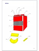
Страница 25: ... 25 8 Parts ...

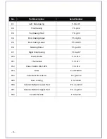
Страница 26: ...wer F h d d 05 06 Steering Panel F h p s 06 07 Right Side Casing F h b p 07 010 Thermometer F h t 010 011 Thermostat F h t 011 012 Power Switch WA 12PS F h ł 012 013 STB F h STB 013 014 Fuse Nest FU max 4A F h g b 014 020 Door Locking F h z d 020 030 Ceramic Deflector Lower Part F h c s d 030 031 Ceramic Deflector Upper Part F h c s g 031 032 Ceramic Nozzle F h d s 032 ...

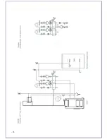
Страница 27: ...systems Open system The bottom of the safety tank must be placed In natural circulation systems or with pump on heating water H 0 3 m over the highest point of the system In systems with pump installed on return water H 0 7Hp m ...

Страница 28: ... 28 ...

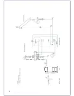
Страница 29: ... 29 Closed systems Warning To collect boiler in closed system it is important to build in the boiler cooling loop and then make a right connection ...

Страница 30: ... 30 ...

Страница 31: ... 31 ...

Страница 32: ... 32 ...

Отзывы: