SIGLENT CP4000 Series Скачать руководство пользователя страница 20

CP6000/CP4000 

18                                                                                                                                                                                    Current  Probe  Instructions 
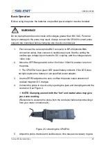
Q&A 

Does CP6000 series fit the oscilloscope of any brand? 

A: CP6000 series has standard BNC interface can be applied to the oscilloscope of 

any brand. It is powered by standard adapter, independent of oscilloscope power, so it 

is very easy to use. 


Can CP6000 series product measure small current? 

A: Yes. For now, the CP6000 series current probe has two optional ranges, and one is 

for small current. The current resolution of the CP6030(A) is 1mA. When measuring 

small current, please accurately zero set and degaussing the probe, and do not change 

the position of the probe hand grip. To observe the waveform please set the bandwidth 

restriction of the oscilloscope to 20MHz to eliminate the interference of noise. When 

measuring extremely small current (a few mA for example), one could make a few more 

loop of cable around the probe and divide the result with number of loop to obtain the 

actual current value. 


Any more tips? 

A: 


When measuring high frequency current, please do not let the current surpass 

the  value  shown  by  the  curve  of  max  peak  current  vs  frequency.  The  max 

continuous current over the curve will burn the probe. 


To  measure  accurately,  please  degauss  and  zero  set  the  probe,  and  make 

sure the probe is locked during the process. 


Set the input impedance of the oscilloscope to 

1MΩ(default) 


Make sure the probe is locked during testing. 


The probe should be away from the interference source like transformer. The 

method to  judge if the  probe  is  interfered is to put the  probe close  to  circuit 

under  test.  IF 

there’s  any  output,  there  could  be  interference  in  the  testing 

environment because the probe is not on the circuit yet. 


The current under test should not surpass the limit value of the probe. 


Please always maintain your probe and do not use it in the humid environment 


If there’s anything wrong with the probe, please set it back for repairing. If you 
dismantled the device on your 

own, we won’t guarantee for repairing. 


Содержание CP4000 Series

Страница 1: ...Current Probe Instructions ...

Страница 2: ......

Страница 3: ...s 14 Operating Method 15 The method to deal with abnormal situation 17 Q A 18 Packing list 19 CP4000 Series Current Probe 20 CP4000 Series Summary 20 General Safety Instructions 20 Safety Terms and Symbols 21 Getting Started 22 CP4000 series controls and indicators 22 Basic Operation 23 Specifications 25 Mechanical Specifications 26 Environmental Characteristics 26 Certifications and compliances 2...

Страница 4: ...n damage to the product or loss of important data Do not proceedbeyond a CAUTION notice until the indicated conditions are fully understood and met A WARNING notice denotes a hazard It calls attention to an operating procedure practice or the like that if notcorrectly performed or adhered to could result in personal injury or death Do not proceed beyond a WARNING notice until the indicated conditi...

Страница 5: ... protective earthling with double insulation construction Do not allow the device to get wet and do not take measurements with wet hands This may cause an electric shock If the waveform measuring instrument being connected to the output terminal BNC on this device is equipped with any other measurement terminals take the following precautions to ensure that the other instrument does not form a bri...

Страница 6: ... precision ground and should be treated with care If these surfaces are scratched performance may be impaired Foreign substances such as dust on the contact surfaces of the sensor head can cause acoustic resonance and degrade measurement so it should be cleaned by gently wiping with a soft cloth To avoid damaging the sensor cable and power supply cable do not bend or pull the cables When the power...

Страница 7: ... resulting from heating of the sensor At high ambient temperatures the built in safety circuit may activate at current input levels below the rated continuous maximum Continuous input of current exceeding the rated maximum or repeated activation of the safety function may result in damage to the unit The probe is rated for maximum input under two conditions in addition to the input maximums shown ...

Страница 8: ... head Depending on the measured current frequency some sound maybe produced by resonance but has no effect on measurements The reading may be affected by the position within the clamp aperture of the conductor being measured The conductor should be in the center of the clamp aperture When carrying out a measurement press the opening lever until the UNLOCK indication disappears and check that the s...

Страница 9: ...input The key features include Highly accurate current measurements current protection with dual indicators buzzer and LED zero setting Applications Switching and linear power design LED lighting design New energy resources Frequency conversion household appliances Experiment of electronic engineering Semiconductor devices design Inverters transformer design Electronic ballast design Industrial co...

Страница 10: ...CP6000 CP4000 8 Current Probe Instructions Description of products 1 CP6030 CP6030A 2 CP6150 CP6500 ...

Страница 11: ...current the red LED will light up and the buzzer will sound an alarm 5 Jaw on indicator When the light is on it means that the push rod is in the unlock state Make sure that the jaw is in the lock state during the measurement 6 Degaussing and Zero Setting Indicator After pressing the degaussing zero button the indicator light will be green and after degaussing the indicator light will be off If de...

Страница 12: ... CP6030 A 30A 0 1V A 5A 1V A CP6150 150A 0 01V A 30A 0 1V A CP6500 500A 0 01V A 75A 0 1V A 10 Power supply socket External power supply socket standard with 12V 1A adapter model CK 612 Accessories Description BNC Cable 100cm MALE X MALE CK 310 Power Adapter 12V 1A CK 612 ...

Страница 13: ...75A 30A 50A 150A 300A 500A 750A Current transfer ratio 5A 1V A 30A 0 1V A 75A 0 1V A 30A 0 1V A 150A 0 01V A 500A 0 01V A Resolution 5A 1mA 30A 10mA 75A 10mA 30A 10mA 150A 100mA 500A 100mA Accuracy DC 45 66Hz 5A 1 1mA 30A 1 10mA 75A 1 10mA 30A 1 10mA 150A 1 100mA 500A 1 100mA Input resistance CP6030 Reference Figure 3 a Reference Figure 6 Reference Figure 9 CP6030A Reference Figure 3 b Delay Probe...

Страница 14: ...P6030 Amp Frequency curve Fig 1 b CP6030A Amp Frequency curve Fig 2 a CP6030 Continuous maximum input measurement Fig 2 b CP6030A Continuous maximum input measurement Fig 3 a CP6030 Input impedance VS Frequency Fig 3 b CP6030A Input impedance VS Frequency ...

Страница 15: ...g 4 CP6150 Amp Frequency curve Fig 5 CP6150 Continuous maximum input measurement Fig 6 CP6150 Input impedance VS Frequency Fig 7 CP6500 Amp Frequency curve Fig 8 CP6500 Continuous maximum input measurement Fig 9 CP6500 Input impedance VS Frequency ...

Страница 16: ...ble length CK 310 100cm Adapter dimensions CK 612 62 58 29mm line 1 5m Clamp dimensions L W H 176 39 5 18mm 174 67 5 30mm Termination unit L W H 91 5 40 26 5mm Probe weight 255g 555g 525g Environmental characteristics Operating temperature and humidity 0 40 80 or less Storage temperature and humidity 10 50 80 or less Operating altitude 2000m Storage altitude 12000m ...

Страница 17: ...e careful when testing sequentially The frequency of the current under test may cause resonance but this won t influence the testing The position of conductor under test in the sensor will influence the result so please move the conductor under test into the center of the sensor Push the switch control pole all the way through until the unlock mark disappear Please make sure the control When disco...

Страница 18: ...ire part through switch controller At the lock state please do not press the entire part as shown below Preparation before testing Prepare the high frequency current probe CP6000 series adapter and oscilloscope Power up the CP6000 probe and the green LED power indicator will be lighted Set the oscilloscope Ground the measuring mode zero set the oscilloscope and turn the oscilloscope mode to DC mod...

Страница 19: ...hen the voltage sensibility of the waveform monitor is 10mV div the current sensibility is 100mA div The method to deal with abnormal situation Situation Possible reason Dealing method Can t measure DC or the value obtained is comparatively low in the frequency range Power is off Turn on power Oscilloscope set to AC coupling Set to DC coupling Sensor is not locked Please lock the sensor Auto degau...

Страница 20: ...result with number of loop to obtain the actual current value Any more tips A When measuring high frequency current please do not let the current surpass the value shown by the curve of max peak current vs frequency The max continuous current over the curve will burn the probe To measure accurately please degauss and zero set the probe and make sure the probe is locked during the process Set the i...

Страница 21: ...CP6000 CP4000 Current Probe Instructions 19 Packing list Packing list ITEM Quantity Probe 1 DC 12V 1A adapter 1 BNC connecting line 1 Instruction manual 1 Guarantee card 1 Test report 1 ...

Страница 22: ...hould perform service procedures To avoid fire or Personal injury Connect and Disconnect Properly Connect the probe output to the measurement instrument before connecting the probe to the circuit under test Disconnect the probe input and the probe ground from the circuit under test before disconnecting the probe from the measurement instrument Observe All Terminal Ratings To avoid fore or shock ha...

Страница 23: ...is manual WARNING Warning statements identify conditions or practices that could result in injury or loss of life CAUTION Caution statements identify conditions or practices that could result in damage to this product or other property Terms on the Product These terms may appear on the product DANGER Indicates an injury hazard immediately accessible as you read the marking WARNING Indicates an inj...

Страница 24: ...te to adjust the probe output to zero when thereis no current present It may also be used to offset a DC signal component Zeroing is not needed for AC measurements unless your instrument cannot isolate a DC component if present OFF Range switch Slide the switch from OFF to either the 10mV A or 100mV A range When either range is selected the probe is turned on and the green battery indicator lights...

Страница 25: ...to DC coupling and the voltage scale to 100m V div 2 Move the OFF Range switch to the 10mV A or 100mV A position to turn on the probe The CP4070A has a green LED power battery indicator If the LED does not light replace the battery or use specified power adaptor 3 Use the ZERO adjustment to zero or offset the probe output detection of residual magnetic DC charges 4 Connect the probe to the circuit...

Страница 26: ...troller Figure 3 Typical current waveform Congratulations on your purchase of CP4000 series a multifunctional current probe When connecting to a digital meter use the recommended MT 246N BNC to banana adapter Connect the black lead to the meter COM and the red lead to the VΩ input To measure only AC current set the meter to measure AC volts To measure DC current set the meter to measure DC volts N...

Страница 27: ...40A 200A 200A Range switch 50mV A 500mV A 50mV A 100mV A 5mV A 50mV A 5mV A 10mV A DC Accuracy Typical 2 0 4A 10ApK at 50mV A 3 20mA 20mA 14ApK at 500mV A 2 0 4A 10ApK at 50mV A 3 50mA 50mA 10ApK at 100mV A 2 1A 60ApK at 5mV A 4 200mA 200mA 100ApK at 50mV A 2 1A 200ApK at 5mV A 4 50mA 500mA 40ApK at 10mV A 15 max 100A 140ApK at 50mV A 15 max 40A 100ApK at 100mV A Power Supply 9V battery Maximum Wo...

Страница 28: ...Conductor size 10 3mm 10 3mm 11mm Cable Length 200cm 100cm 100cm Weight 310g 310g 260g Environmental Characteristics Model CP4020 CP4070 CP4050 CP4070A Operating Temperature 0 50 32 F 122 F Nonoperating Temperature 20 80 20 F 80 F Humidity 0 40 95 RH 40 50 45 RH Pollution Degree 2 CP4050 Gain versus frequency at 1A peak CP4070A Gain versus frequency at 1A peak ...

Страница 29: ... Maximum current versus frequency CP4070A Maximum current versus frequency CP4050 DC signal linearity in the 50mV A range CP4070A DC signal linearity in the 10mV A range CP4050 Phase versus frequency at 1A peak CP4070A Phase versus frequency at 1A peak ...

Страница 30: ...ation categories are CAT III Distribution level mains usually permanently connected Equipment at this level is typically in a fixed industrial location CAT II Local level mains wall sockets Equipment at this level includes appliances portable tools and similar products Equipment is usually cord connected CAT I Secondary Signal level or battery operated circuits of electronic equipment Pollution De...

Страница 31: ...and put it in cool clean and dry places 4 Please put the probe in the package provided to prevent shock 5 Do not forcefully pull the input and output lead to prevent bending twisted and folding Contact SIGLENT SIGLENT TECHNOLOGIES CO LTD Address 3 F Building 4 Antongda Industrial Zone Liuxian Road 68 District Baoan District Shenzhen P R CHINA Service Tel 0086 755 3661 5186 Post Code 518101 E mail ...

Страница 32: ...as launched in 2005 SIGLENT has become the fastest growing manufacturer of digital oscilloscopes We firmly believe that today SIGLENT is the best value in electronic test measurement Headquarters SIGLENT Technologies Co Ltd Add Bldg No 4 No 5 Antongda Industrial Zone 3rd Liuxian Road Bao an District Shenzhen 518101 China Tel 86 755 3688 7876 Fax 86 755 3359 1582 Email sales siglent com Website int...

Отзывы: