


13
uniform and free of any loose glass. Be careful not to sand the
paint on the outside of the cowl. Remove all fiberglass dust from
the cowl with tac rag or with alcohol on a clean cloth.
❑
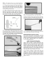
5) We recommend a 3-1/4" dia. aluminum spinner (not
supplied) for the SUKHOI.
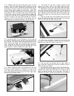
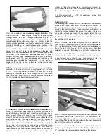
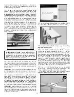
TAIL SURFACES
The following instructions depict the installation of dual elevator
servos and a single rudder servo, all mounted at the rear of the
fuselage. This provides the simplest, most direct linkage from the
servos to the control surfaces. There are cutouts provided in the
rear of the fuselage sides for the servos. If you look closely you
can see the cutouts underneath the covering material. The two
elevator servos go in the two uppermost cutouts, right underneath
the stabilizer. The single rudder servo goes in the lower cutout on
the right side of the airplane.
NOTE: Some fliers prefer to use a pull-pull cable system for the
rudder, with the rudder servo mounted in the front of the airplane.
For those that prefer that method we have provided a single servo
tray in the front of the fuselage for the rudder servo. No other
materials are provided for making a pull-pull cable rudder hookup.
❑
1) Use a sharp #11 blade to open up the two elevator servo
cutouts and the rudder servo cutout at the rear of the fuselage.
Use a trim seal iron to tack the loose covering around into the
cutouts. Trim and remove the excess covering material.
NOTE: Accurate alignment is ultra critical to the performance of
an aerobatic airplane like the SUKHOI.
For that reason, we
recommend that you buy or borrow an accurate "incidence meter"
(like a Robart
®
Incidence Meter) to help with the final alignment of
the tail surfaces during the next steps.
❑
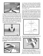
2) Use a ruler to find the exact center of the stabilizer at the
trailing edge, marking the location with a felt-tip pen. Then use a
90
O
triangle to draw a centerline on the stab at this location.
❑
4) You need to cut adaquete size openings in the bottom of the
SUKHOI cowling to allow engine cooling air to properly flow
through and exit the cowl.
Cooling a fully cowled engine is not
difficult, although many modelers have trouble doing it.
It's
relatively simple if you follow one basic rule. Simply stated, the
total square inches of area you have for air exit must be equal to,
or slightly more than, the square inches of area you have in the
front of the cowl (with the spinner in place) for air to come in. In
other words, ALL the air that comes in the front of the cowl, must
have room to get out! Some air will escape around the sides and
bottom of the cowl, but that is not enough. Additional openings in
the bottom of the cowling are absolutely necessary for proper
cooling! Without these additional openings, your engine may
overheat and quit. The exact dimensions and locations of the
openings may certainly be "customized" for your particular
engine/muffler set-up, as long as there is sufficient total square
inches of air exit area.
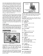
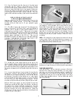
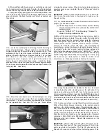
NOTE:
In this picture of our FPE 2.4 gas engine installation,
notice the 1-1/2" wide x 3-3/4" long cooling opening, a 1-1/2" wide
x 2-1/2" long cooling opening, another 1-1/2" wide x 2-1/2" long
opening for the muffler pipes to stick through, and a 7/8" dia. round
hole for the spark plug to stick out. All of these holes contribute to
the total square inches of cooling air exit area.
TIPS ON CUTTING HOLES IN A FIBERGLASS COWLING: First
of all, be sure to wear safety glasses and a mask of some kind to
avoid inhaling any fiberglass dust. Use a fine-point marker pen to
draw an exact outline of the area you want to cut out. Then use a
Dremel
®
Tool and a large cut-off wheel to remove the bulk of the
area inside the lines. If you are careful, you will find that you can
get fairly close to the lines with the cut-off wheel. The goal is to
remove most of the material within the lines. Once the majority of
the area is cut and removed, exchange the cut-off wheel for a
sanding drum bit in your Dremel
®
Tool. Use the drum sander to
finish the edge right up to the line. Finally, use 220 sandpaper by
hand to clean up any jagged edges. Make sure all edges are
Содержание SUKHOI SU-31 ARF
Страница 23: ...23 ...