


in mind that for best control response the gap should be kept as
small as possible, but big enough to allow full movement of the
control surface. Make sure everything is functioning properly be-
fore proceeding to the next step.
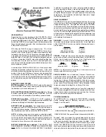
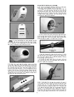
e) Carefully place three or four drops of Thin CA glue directly
onto the hinge in the gap. You will notice that the glue is quickly
wicked into the slot as it penetrates both the wood and the hinge.
Turn the part over and glue the other side of the hinge. Continue
this process until you have glued both sides of all three hinges.
Keep a rag handy to wipe off any excess Thin CA glue. (If you
get some glue smears on the plastic covering, don't worry about
them right now. Once all the hinging is done, you can clean the
smears off the covering with CA Debonder). Let the glue dry a
minimum of 5 minutes before flexing the hinges.
VERY IMPORTANT: It's critical that you only make one applica-
tion of glue to each side of a CA Hinge. If you apply additional
glue to the hinge after the first application of glue is already dry,
the second application of glue will merely puddle in the hinge gap
and make the hinge too stiff to operate properly. When properly
glued, the portion of the hinge that you can see in the hinge gap
should have a dry appearance, not wet. Two to three good size
drops of Thin CA should be about the right amount. NEVER USE
CA ACCELERATOR ON CA HINGES!
❑
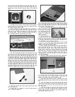
15) Screw the Brass Bearing Plate of the tailwheel assembly
in place on the bottom of the fuselage, using the (2) M2 x 8mm
PWA Screws provided. Drill pilot holes first.
ELEVATOR & RUDDER HOOKUP
For this section you will need the Fuselage, (2) Servos, (2) Long
Formed Wire Pushrods, and (2) Nylon Pushrod Keepers.
❑
16) Mount the elevator and rudder servos in the fuselage,
using the screws that came with the servos.
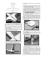
a) Begin by positioning the servos in place in the plywood
servo tray built into the fuselage. Make sure the ends of the servo
arms line up with the plastic pushrod tubes already installed in
the fuselage.
b) Once you have the servos correctly positioned, drill small
pilot holes through the plywood for each servo mounting screw.
We used a small pin vise and a .040" (#60) drill bit to make these
pilot holes. Then, use a small screwdriver to install the servo
mounting screws.
❑
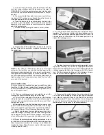
17) Study the following photo to become familiar with the in-
stallation of the formed pushrod wires. Notice that the Z-bend in
the end of the pushrod will be installed down through the top of
the servo arm.
a) Now slide the pushrod wires inside the appropriate plastic
pushrod tubes in the fuselage.
b) Remove the servo arms from the servos. Install the servo
arms on the Z-bend ends of the pushrod wires (if the holes in your
servo arm are too small for the wire, drill out the holes with a #60
or 3/64" dia. drill bit). Then, reinstall the servo arms back onto the
servos. Do not tighten the servo arm screws completely yet be-
cause the arms may have to be repositioned when the radio sys-
tem is tested and centered.
❑
18) Next step is to complete the aft end of the rudder pushrod.
Start by centering the rudder servo output arm in neutral position.
Use small pieces of tape to hold the rudder in neutral position.
a) Slide one of the nylon pushrod keepers over the aft end of
the rudder pushrod wire.
b) Hold the rudder pushrod wire against the side of the nylon
control horn and use a fine tip pen to mark the exact position of
the control horn hole on the wire. NOTE: The wire will be installed
in the middle hole of the control horn.
8