


first in order to avoid "dimpling" the face of the firewall with the bolt
head).
If desired, the blind mounting nuts can be permanently adhered to
the backside of the firewall by using a little 5-minute epoxy on your
finger to spread the glue around the outside edges of each nut. Do
not get glue into the threaded centers.
❑
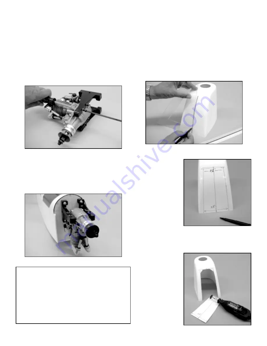
5) Temporarily mount the engine to the two motor mount arms,
using your own hardware (again, we suggest socket head
hardened steel bolts with lock nuts, as shown).
Because the
engine will have to be removed in the following steps, don't tighten
the bolts yet - just enough to get the engine sitting firmly in place
on the motor mount arms.
Apply a little threadlock compound to each of the M4 x 25mm
mounting bolts. Slip a split ring washer and a M4 washer onto
each bolt. Hold the engine/motor mount assembly in place to the
firewall and install each bolt in place to hold the assembly to the
firewall. Allow enough play in the bolts to be able to slide the motor
mount arms left or right, as needed, to center the motor mount
bases to the firewall. When everything looks about right, firmly
tighten the bolts.
❑
6) From the kit contents, locate the bag containing the
Fiberglass Cowl and mounting screws. The cowl is now prepared
to fit in place over the engine and onto the cowl. In the case of our
inverted engine, this requires that the bottom of the cowl be
opened to clear the engine head and to provide adequate cooling.
Always remember to wear a face mask and eye protection when
working with and cutting fiberglass parts.
Begin by placing the cowl on a flat surface, with the nose up. Use
a ruler and a pencil or non-permanent marker pen to place a mark
at the bottom center. Use a 90
O
triangle to then make a vertical
line straight up the middle of the cowl bottom. This line becomes
the reference line for the required opening.
Since the overall width of
the Saito 1.50, at the
head, is about 2-1/4", we
know that the opening
must be at least that wide.
When creating this
opening, the idea is to
neatly expose as much
cooling air to the cylinder
head as possible.
As
shown, we used a width
of 3-1/2" at the back of the
cowl, tapering up to 2-1/2"
wide at the top of the
opening.
After making
the measurements, connect the marks with a non-permanent pen
and a flexible straight edge, such as a strip of balsa. At the top of
the opening there are two corners. Use a circle guide to draw
radiuses at these two corners.
With the outline of the
opening now drawn onto
the cowl, the actual
opening is now made. To
do this neatly and quickly,
we suggest using a
Dremel
®
Tool. Start with a
carbide cut-off wheel to
first remove the major
piece of fiberglass within
the outline.
12
TOOLS 101:
We've all heard stories about "inferior foreign metric hardware".
Unfortunately, much of this bias tends to come from individuals
who use the wrong tools to do the job! For example, there are
many types of Phillips screwdriver bits. Use too small of a
screwdriver bit in a Phillips head bolt and you will almost always
roach out the head. When working with Phillips head hardware,
choose a screwdriver that completely fits and fills the Phillips
head openings. Likewise, oversized screwdriver bits will also
ruin the bolt head. Choose your tools with care, and use them
the way they were intended.