SIG 4-STAR 64 EG ARF Скачать руководство пользователя страница 9

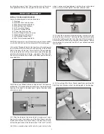
19) Slide the Nylon Rudder Steering Clasp onto the bottom of

the rudder and onto the tailwheel wire at the same time.  Locate
the clasp at the halfway point on the wire, and then drill a hole for
the M2 x 15mm Bolt.  Insert the bolt through the hole and tighten
down the M2 Hex Nut to clamp the bracket in place.

20) Look closely and you will find three holes pre-drilled near

the bottom of the rudder for mounting a nylon control horn.  Install
the control horn on the left side of the rudder, with the retaining
plate on the right, using three M2 x 14mm screws.

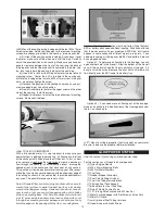
21) Look closely and you will find three holes pre-drilled in one

of the elevators for mounting a nylon control horn.  Screw the con-
trol horn in position on the bottom of the right elevator using three
M2 x 14mm screws.

ELEVATOR & RUDDER CONTROLS

For this section you will need:

    (1) Fuselage Assembly
    (2) 35.5" long Wire Pushrods with M2 Hex Nut
    (2) Metal RC Clevis
    (2) small pieces of Fuel Tubing
    (2) Pushrod Snap Keepers
    (1) Radio Receiver (not furnished)
    (2) Servos with Mounting Screws (not furnished)

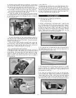
22) Install the rudder and elevator servos inside the fuselage in

the  built-in  plywood  radio  mounting  tray.    Note  that  the  rudder
servo goes on the right side of the airplane, and the elevator servo
goes on the left side.  (The servo opening in the center is for the
throttle servo in a glow installation.)  Be sure to drill pilot holes
through the plywood tray for the mounting servo mounting screws.

23) Mount your receiver in a place of your choosing.  If using a

glow engine it is recommended that you wrap the receiver in foam
rubber to protect it from vibrations.

24) If you are using a receiver battery pack, mount your on/off

switch in the fuselage side.  Note that there are precut holes in
the fuselage sides, underneath the covering material, for either a
standard size switch or a super switch with built-in charging plug.
Cut  away  the  covering  over  the  hole  that  fits  your  switch  and
mount using the screw supplied with your switch.  

25) Assemble and install the rudder pushrod.

    a) First slide a small piece of Fuel Tubing onto the small end of

the  Metal  R/C  Clevis.    Next  screw  the  Hex  Nut  that  is  on  the
Pushrod Wire all the way up to the end of the threads.  Then screw
the metal clevis halfway onto the threads.

    b) Locate the precut pushrod exit hole for the rudder on the left

side of the fuselage at the back of the plane. Slide the pushrod
into the sleeve and attach the clevis to the control horn.  Center
the rudder and hold it in place with a couple pieces of tape so it
cannot move.

    c) Inside the fuselage, hold the pushrod wire over the rudder

servo output arm and mark the wire where it crosses over the
outer hole in the servo arm.

9

Содержание 4-STAR 64 EG ARF

Страница 1: ...andard Servos glow 4 Channel with 4 Standard Servos electric Glow Power 2 Stroke 60 75 cu in 10 0 12 3 cc 4 Stroke 60 90 cu in 10 0 14 7 cc Electric Power 1200 1700 watt Brushless Motor 400 600 kv 75A Speed Control ESC 4 6S 4000 5000 mAh Lipo Battery Pack SIG MFG CO INC PO Box 520 Montezuma IA 50171 0520 www sigmfg com Copyright 2013 SIG Mfg Co Inc KIT NO SIGRC73EGARFR red SIGRC73EGARFY yellow ...

Страница 2: ...our particular ESC to learn if this is true in your case If your BEC is not rated for your battery choice you have three op INTRODUCTION Congratulations on your purchase of the SIG 4 STAR 64 EG ARF We hope you will enjoy this unique fun scale R C model Assembly of your 4 STAR 64 EG ARF is fast and simple when following the detailed instructions in this manual We urge you to read this assembly manu...

Страница 3: ... cycle This translates to better flight times and a longer life from the battery pack REQUIRED TOOLS For proper assembly we suggest you have the following tools and materials available A selection of glues SIG Thin Medium Thick CA Glue CA Accelerator CA Debonder SIG Kwik Set 5 Minute Epoxy Screwdriver Assortment Pliers Needle Nose Flat Nose Diagonal Wire Cutters Small Allen Wrench Assortment Pin V...

Страница 4: ...eter you can find the correct tem perature by trial and error Set your iron to a medium setting Glide the iron over some of the covering that is over solid wood such as the sheeted wing center section Observe the covering to see if any bubbles appear If bubbles appear the covering is getting too hot Turn down the temperature of the iron and repeat the test If no bubbles appear turn up the heat sli...

Страница 5: ...u can get it to fall through the openings in the ribs until it emerges at the end rib Once you ve got the plug to the end rib direct it through the round hole in the bottom surface of the wing panel By that time the servo itself should be next to the servo mount cutout and ready for mounting f Fit the servo into the servo mount in the wing panel note that the servo is positioned so that the servo ...

Страница 6: ...of Fuel Tubing onto the small end of the Metal R C Clevis Screw the Hex Nut on the Aileron Pushrod Wire all the way up to the end of the threads Then screw the metal clevis halfway onto the threaded end of the Aileron Pushrod Wire b Clip the metal clevis into the last hole in the nylon control horn Lay the other end of the pushrod wire over the outer hole in the servo arm Use a felt tip pen to mar...

Страница 7: ...arrow notch in the wheel pants when they are added later 6 Slide a 4mm Wheel Collar onto the axle shaft but leave ap proximately 1 4 of space between it and the nut to provide proper spacing of the wheel in the wheel pant Tighten the wheel collar set screw securely 7 Slide the wheel on the axle and test to make sure it spins freely on the axle Next slide one of the Main Wheels onto the axle and te...

Страница 8: ... glue to both sides and reset the stab in place Use pins to hold it in place Re check the alignment Wipe away any excess epoxy with rubbing alcohol and a soft paper towel Allow the glue to set completely 14 Pull the Fin and Rudder apart set the rudder and hinges aside for now Test fit the fin in place on top of the stabilizer Check to see that the fin sits flush and perpendicular to the stabi lize...

Страница 9: ...o goes on the left side The servo opening in the center is for the throttle servo in a glow installation Be sure to drill pilot holes through the plywood tray for the mounting servo mounting screws 23 Mount your receiver in a place of your choosing If using a glow engine it is recommended that you wrap the receiver in foam rubber to protect it from vibrations 24 If you are using a receiver battery...

Страница 10: ... furnished NOTE The mounting of the electric motor in the 4 STAR 64 as sumes that your motor has a typical X or cross mounting plate on the back of the motor Also note that the firewall portion of the laser cut plywood motor mount is adjustable fore and aft to ac commodate different length motors Next we will determine where you should set the firewall for your particular motor 27 Assemble your mo...

Страница 11: ...ither of these are pro vided c Now route the ESC s servo wire back to the receiver and plug it in d Connect the ESC s motor wires to the motor Operate the motor and check the direction of rotation Always do this without a propeller attached If you need to reverse the rotation refer to the instructions that came with the motor and ESC SAFETY ISSUE We strongly recommend the use of an arming switch f...

Страница 12: ...l or similar rotary hand tool with an assort ment of bits is without a doubt the best tool to use for making cutout in the fiberglass cowling However if you do not have ac cess to such a tool you can cut the opening with a drill a hobby knife and a sanding block First first drill a series of almost touch ing 1 8 holes inside the pattern lines then use the knife to cut through the connecting materi...

Страница 13: ...serting its bottom tabs into the slots in the plywood fuel tank tray We sug gest you only spot glue the tank support in place at the top so it can be removed later if you ever need to service the fuel tank f Glue the balsa block fuel tank stop in place on the plywood tank tray up against the rear end of the tank 40 Bolt the two Nylon Engine Mounts on the front of the fire wall using M4 x 30mm Bolt...

Страница 14: ... to the throttle servo 14 45 COWLING Some glow engine fliers do not use the supplied Fiberglass Cowl ing preferring to keep the front of the airplane open for easy ac cess to the engine for fueling and service If you do want to use the cowling you will need to cut a large opening in the top of the cowling for the engine head to stick out Step 35 on page 12 of this manual describes mounting the cow...

Страница 15: ...st point of the control sur face Adjust for HIGH RATES first using mechanical means rather than your transmitter end point adustment to get as close as possible to the recommended travel By moving the position of the clevis at the control horn toward the outermost hole you will decrease the amount of control throw of the control surface Moving it toward the control surface will increase the amount...

Страница 16: ...d actions of the builder flyer of this model airplane kit will ultimately determine the airworthiness flight performance and safety of the finished model SIG MFG CO s obligation shall be to replace those parts of the kit proven to be defective or missing The user shall determine the suitability of the product for his or her intended use and shall assume all risk and liability in connection therewi...

Отзывы: