


to the throttle servo and the engine’s throttle arm. In most cases
you will want the pushrod to run right alongside the engine mount
and fuel tank, and then angle over to the throttle servo arm.
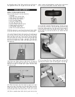
d) Drill a hole through the firewall for the nylon pushrod tube
to pass through. Be careful not to drill a hole in your fuel tank!
e) Install the metal pushrod keeper in the throttle servo arm,
with one hex nut above the arm, and one below.
f) Slide the pushrod into the airplane from the front until you
can clip the metal RC clevis to the engine throttle arm. Be sure
to install the small piece of fuel tubing over the arms of the clevis
so it cannot come off.
g) Check the movement of the throttle pushrod by working it
from the servo end, to determine how much of the nylon pushrod
tube should stick out in front of the firewall. Then glue the nylon
pushrod tube to the firewall.
h) Turn on your radio and adjust the length and travel of the
throttle pushrod. Note: You may find it necessary to support the
servo end of the nylon pushrod tube with a scrap of balsa, ply-
wood, or foam - to keep the pushrod from flexing.
❑
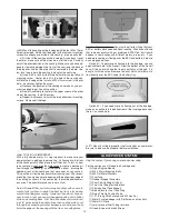
44) 4-STROKE THROTTLE PUSHROD
4-Stroke glow engines typically have their carburetor on the back
of the engine. This puts the throttle arm very close to the firewall
of the airplane. You will probably find it works best for a 4-stroke
engine to reverse the supplied pushrod so that the pushrod
keeper is hooked to the carburetor and the RC clevis is hooked to
the throttle servo.
14
❑
45) COWLING
Some glow engine fliers do not use the supplied Fiberglass Cowl-
ing, preferring to keep the front of the airplane open for easy ac-
cess to the engine for fueling and service. If you do want to use
the cowling you will need to cut a large opening in the top of the
cowling for the engine head to stick out. Step 35) on page 12 of
this manual describes mounting the cowling.
For this section you will need the Fuselage and:
(1) Painted Pilot Figure
(1) Clear Plastic Canopy
❑
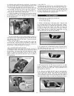
46) Test fit the pilot figure in the cockpit area. Check to make
sure that the canopy will fit over the pilot and reposition if needed.
Once you have the pilot in a good position trace around the base
of the pilot with a felt pen. Using a razor blade, cut through the
covering just inside your markings so you can expose the bare
wood. Exposing the balsa will provide a stronger bond, insuring
that the pilot will not “bail out” during aerobatics.
❑
47) Using epoxy or a silicone based adhesive, glue the pilot to
the cockpit base and let it dry. It is not recommended to use CA
glue as it may break loose over time.
❑
48) Double check the fit of the canopy to make sure it is ready
to install. Make any final changes to the cockpit area at this time.
Make sure the canopy is clean inside. Once it’s glued down it will
be impossible to clean later.
❑
49) Once you are happy with the fit, glue the canopy perma-
nently in place on the fuselage. We recommend using a dedicated
“canopy glue” such as RC56. It dries clear yet remains flexible.
Put a small bead of glue all around the canopy on the inside of
the black trim area. Make sure there is sufficient glue to make a
PILOT & CANOPY