Offset
Name
Description
0x00
pwmcfg
PWM configuration register
0x04
Reserved
0x08
pwmcount
PWM count register
0x0C
Reserved
0x10
pwms
Scaled PWM count register
0x14
Reserved
0x18
Reserved
0x1C
Reserved
0x20
pwmcmp0
PWM 0 compare register
0x24
pwmcmp1
PWM 1 compare register
0x28
pwmcmp2
PWM 2 compare register
0x2C
pwmcmp3
PWM 3 compare register
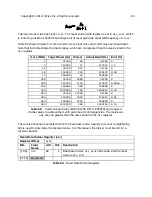
The PWM unit is based around a counter held in
pwmcount
. The counter can be read or written
over the TileLink bus. The
pwmcount
register is
bits wide. For example, for
cmpwidth
of 16 bits, the counter is held in
pwmcount[30:0]
, and bit 31 of
pwmcount
returns a
zero when read.
When used for PWM generation, the counter is normally incremented at a fixed rate then reset
to zero at the end of every PWM cycle. The PWM counter is either reset when the scaled
counter
pwms
reaches the value in
pwmcmp0
, or is simply allowed to wrap around to zero.
The counter can also be used in one-shot mode, where it disables counting after the first reset.
PWM Count Register (
pwmcount
)
Register Offset
0x8
Bits
Field Name
Attr.
Rst.
Description
[30:0]
pwmcount
RW
X
PWM count register.
cm 15
bits wide.
31
Reserved
Table 89:
SiFive PWM memory map, offsets relative to PWM peripheral base address
Table 90:
PWM Count Register
Copyright © 2019, SiFive Inc. All rights reserved.
96
Содержание FE310-G002
Страница 1: ...SiFive FE310 G002 Manual v19p05 SiFive Inc ...
Страница 11: ...Figure 1 FE310 G002 top level block diagram Copyright 2019 SiFive Inc All rights reserved 9 ...
Страница 15: ...Chapter 2 List of Abbreviations and Terms 13 ...
Страница 23: ...Chapter 4 Memory Map The memory map of the FE310 G002 is shown in Table 4 21 ...


