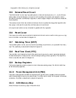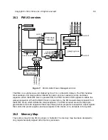
The FE310-G002 can be reset by pulling down on the external reset pin (
erst_n
), which has a
weak pullup. An external power-on reset circuit consisting of a resistor and capacitor can be
provided to generate a sufficiently long pulse to allow supply voltage to rise and then initiate the
reset stretcher.
The external reset circuit can include a diode as shown to quickly discharge the capacitor after
the supply is removed to rearm the external power-on reset circuit.
A manual reset button can be connected in parallel with the capacitor.
The cause of an AON reset is latched in the Reset Unit and can be read from the
pmucause
reg-
ister in the PMU, as described in Chapter 15.
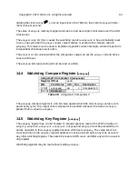
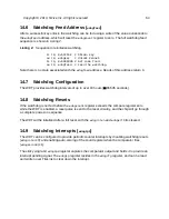
The watchdog timer can be used to provide a watchdog reset function, or a periodic timer inter-
rupt. The watchdog is described in detail in Chapter 14.
The real-time clock maintains time for the system and can also be used to generate interrupts
for timed wakeup from sleep-mode or timer interrupts during normal operation. The Real-Time
Clock is described in detail in Chapter 16.
The backup registers provide a place to store critical data during sleep. The FE310-G002 has
32 32-bit backup registers.
The power-management unit (PMU) sequences the system power supplies and reset signals
when transitioning into and out of sleep mode. The PMU also monitors AON signals for wakeup
conditions. The PMU is described in detail in Chapter 15.
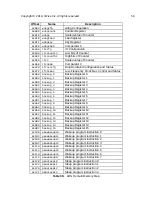
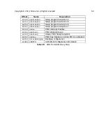
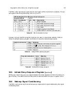
Table 36 shows the memory map of the AON block.
Copyright © 2019, SiFive Inc. All rights reserved.
58
Содержание FE310-G002
Страница 1: ...SiFive FE310 G002 Manual v19p05 SiFive Inc ...
Страница 11: ...Figure 1 FE310 G002 top level block diagram Copyright 2019 SiFive Inc All rights reserved 9 ...
Страница 15: ...Chapter 2 List of Abbreviations and Terms 13 ...
Страница 23: ...Chapter 4 Memory Map The memory map of the FE310 G002 is shown in Table 4 21 ...


