Sierra Wireless AirPrime WP7504 Скачать руководство пользователя страница 18

Hardware Integration Guide

Specifications subject to change

18

4119157

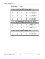
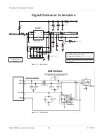
Signal Reference Schematics

Figure 4-2:  UIM Interface

Figure 4-3:  USB Interface

0

0

0

0

10nF

0

100nF

10

C3

C2

C1

9

C7

C6

C5

GND
VPP
I/O

SW_A

VCC

RST

CLK

SW_B

DNI

DNI

DNI

VGPIO_1V8

UIM_RESET_N

UIM_DATA

UIM_CLK

UIM_VCC

UIM1_DET

UIM1

DNI

SIM2070-6-0-30-00-A

ESD suppressor

Note:

 Example ESD and SIM connector part numbers listed. 

Comparable parts may be used instead.

Note:

 Capacitor on UIM_CLK is intended to slow down the 

clock signal in case of crosstalk.

DNI

DNI

Example ESD suppressor:

STMicroelectronics

DALC208SC6


+

uClamp 3301P

1

2

3
4
6

5

Important:

 SIM connector must have a ‘Normally closed’ 

detection switch.

Содержание AirPrime WP7504

Страница 1: ...AirPrime WP7504 Hardware Integration Guide 4119157 Rev 1...

Страница 2: ......

Страница 3: ...aircraft the Sierra Wireless modem MUST BE POWERED OFF When operating the Sierra Wireless modem can transmit signals that could interfere with various onboard systems Note Some airlines may permit the...

Страница 4: ...diaries Windows is a registered trademark of Microsoft Corporation QUALCOMM is a registered trademark of QUALCOMM Incorporated Used under license Other trademarks are the property of their respective...

Страница 5: ...mendations 13 PCB Layout Recommendations 13 Power Supply 13 Antenna 14 PCB Specifications for the Application Board 14 Recommended PCB Land Pattern 14 Routing Constraints 14 Power Supply 14 UIM Interf...

Страница 6: ...Hardware Integration Guide Specifications subject to change 6 4119157 Important Compliance Information for North American Users 22...

Страница 7: ...PA WCDMA and CDMA networks The module also provides GNSS functionality as a SKU configuration Accessories A hardware development kit is available for AirPrime WP series modules The kit contains hardwa...

Страница 8: ...Hardware Integration Guide Specifications subject to change 8 4119157...

Страница 9: ...orted Power States State Description Wake Up Events OFF Module is off no power to the system Apply power for system to go to Active state Apply power Interrupt Simple wakeup sources are configured to...

Страница 10: ...Hardware Integration Guide Specifications subject to change 10 4119157...

Страница 11: ...A channel spacing is 5 MHz but this can be adjusted to optimize per formance in a particular deployment scenario Band Frequency Tx MHz Frequency Rx MHz B2 1850 1910 1930 1990 B4 1710 1755 2110 2155 B5...

Страница 12: ...lass 3 B17 22 23 24 Connectorized Class 3 B25 22 23 24 Connectorized Class 3 B26 22 23 24 Connectorized Class 3 Table 3 6 Conducted Tx Max Output Power Tolerances WCDMA RF band Min dBm Typ dBm Max dBm...

Страница 13: ...pads should be re flowed on to the host PCB with 30 voiding to allow effective heat dissipation Power Supply When designing the power supply make sure that VBAT_BB VBAT_RF meet the requirements liste...

Страница 14: ...tected by ground planes fills Routing sensitive signals close to noisy signals could result in noise being coupled Recommended PCB Land Pattern Refer to the AirPrime WP8548 Customer Process Guidelines...

Страница 15: ...ed directly under the module This will Ensure high current signal returns Provide heat dissipation under higher operating temperatures The ground plane should be connected with vias to the reference g...

Страница 16: ...round the module Locate the module away from other components that generate heat Ensure the module is connected to a solid ground plane EMC and ESD Recommendations EMC tests must be performed on the a...

Страница 17: ...ard layout Providing sufficient space around the module for heat dissipation Table 4 1 ESD specifications 1 2 1 ESD specifications are preliminary subject to change 2 ESD protection is highly recommen...

Страница 18: ...I VGPIO_1V8 UIM_RESET_N UIM_DATA UIM_CLK UIM_VCC UIM1_DET UIM1 DNI SIM2070 6 0 30 00 A ESD suppressor Note Example ESD and SIM connector part numbers listed Comparable parts may be used instead Note C...

Страница 19: ...cations subject to change Figure 4 4 USB OTG Interface 2 1 5 3 4 6 6 4 2 5 7 1 3 51K 5 51K 5 51K 5 470 1 NC1 VCC NC2 GND A Y VCC_1V8 VCC_5V0 USB_ID DNI VCC_1V8 10 F USB_VBUS VIN VOUT FLAGB ISET ON GND...

Страница 20: ...Hardware Integration Guide Specifications subject to change 20 4119157...

Страница 21: ...data Safety and Hazards Do not operate your AirPrime WP7504 Embedded Module In areas where blasting is in progress Where explosive atmospheres may be present including refueling points fuel depots and...

Страница 22: ...th FCC IC regulations limiting both maximum RF output power and human exposure to RF radiation the maximum antenna gain including cable loss in a mobile only exposure condition must not exceed the lim...

Страница 23: ...d to ensure compliance with current FCC IC RF exposure guidelines The end product with an embedded AirPrime WP7504 module may also need to pass the FCC Part 15 unintentional emission testing requireme...

Страница 24: ......

Отзывы: