Siemon PowerMax™ User Manual v1.3.0
27
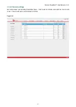
3.3.4 Network Settings
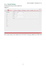
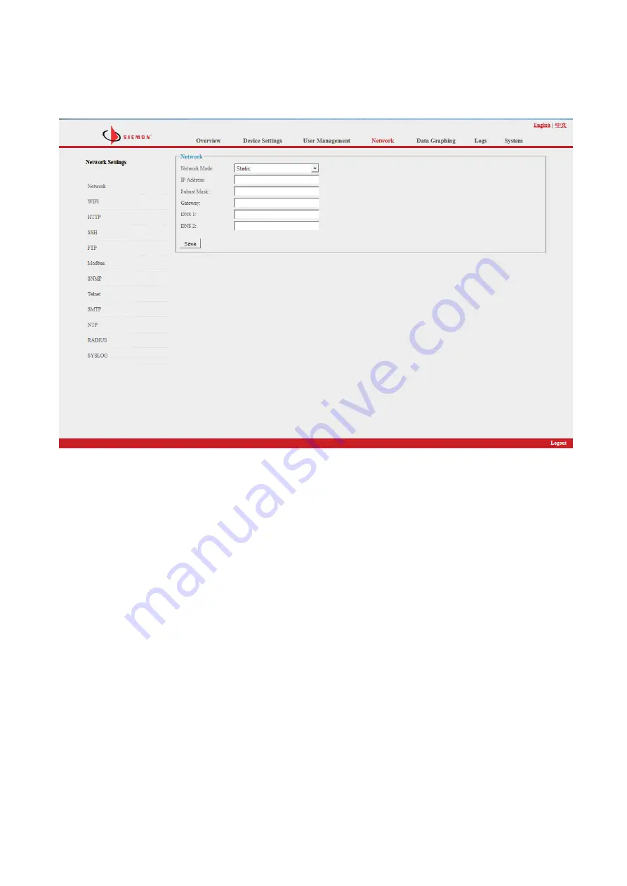
Click Network Settings from the navigation bar.
Figure 3-14
Note: network settings include Network, WIFI, HTTP, SSH, FTP, Modbus, SNMP, Telnet, SMTP, NTP,
Страница 1: ...Intelligent Power Distribution Unit PDU User Manual V1 3 0 ...
Страница 2: ...nstallation 8 1 4 1 Vertical Mounting 0U 8 1 4 2 Horizontal Mounting 1U 8 2 Hardware Introduction 9 2 1 System initialization 9 2 2 View system information 9 2 3 Overload Monitoring 11 2 3 1 Outlet level 11 2 3 2 PDU level 11 2 4 Environment monitoring 11 2 5 PDU reset 11 2 6 Display backlight always on configuration 11 2 7 Invert the display 11 2 8 Restore to factory settings 11 2 9 Master or Sla...
Страница 3: ... command 47 3 4 3 Set command 49 3 4 4 Network command 52 3 4 5 Reboot Command 53 3 4 6 RESET command 54 3 4 7 QUIT command 55 3 5 MODBUS Access 55 4 Frequently Asked Questions 55 4 1 Forgot IP address 55 4 2 Failed to send email 55 4 3 Lost IP 55 5 Technology Parameters 56 6 Warranty and Service 57 6 1 Technical service 57 6 2 General policies 58 ...
Страница 4: ...ning outlet state Keep the on off condition of each outlet after resetting 1 1 4 User defined alarms Set the threshold of current temperature and humidity alarms 1 1 5 System default alarms Send a warning when the total PDU current or individual current Smart and Managed only are exceeded also for sensors 1 1 5 1 Alarm methods Alarm information shown on LCD screen Audible buzzer Alarm parameter va...
Страница 5: ...ion Switched and Managed Switching On Off each individual outlet power on off delay Return to zero for total or individual power consumption configure scheduled events overload power cut off settings quick mass setup of PDUs back up WIFI settings Outlet state settings Outlet on off state maintained after restart Switched and Managed User defined alarm User defined alarms total current individual c...
Страница 6: ... 7 ENTER button select 8 RUN indicator 9 1600imp kWh Energy pulse indicator 10 RESET button 11 USB port for WIFI access or software upgrade 12 NET 10 100M Ethernet communication port 13 SER Serial communication port supporting MODBUS 14 IN for daisy chain 15 OUT for daisy chain 16 T H1 temperature and humidity sensor port 1 17 T H1 temperature and humidity sensor port 2 18 SENSOR extend sensor hub...
Страница 7: ...t page 6 UP button scroll up to the previous page 7 NET 10 100M Ethernet communication port 8 SER Serial communication port support MODBUS 9 IN for daisy chain 10 OUT for daisy chain 11 USB port for WIFI access or software upgrade 12 RESET button 13 LED indicator 14 Outlets 15 Anti trip 16 T H1 T H2 temperature and humidity sensor port1 and port 2 17 Fixed screw 1 14 15 3 16 16 4 5 17 13 7 8 9 11 ...
Страница 8: ... 0 8 1 4 Installation 1 4 1 Vertical Mounting 0U 1 4 2 Horizontal Mounting 1U Horizontally mountable PDUs mount according to EIA ECA 310 E standards and are compatible with any equivalent 19 rack or cabinet utilizing standard hardware ...
Страница 9: ...tion Device information Total Total power data Tem Hum Temperature Humidity Sensors Door Water sensors the second page of the menu Output Outlet socket Group Outlet group Use the DOWN or UP button to scroll down or up to the next previous page return to the main menu and select the first item Information then press ENTER to go to the Information menu The displayed information is as follows CPU CPU...
Страница 10: ...ct Temp Hum to view the temperature humidity as below T1 H1 T2 H2 T3 H3 T4 H4 Press ENTER to return to the main menu then press DOWN key to select Sensors to view the door water smoke sensor status as below Door1 None Door2 None Smoke None Water None Press ENTER to return to the main menu then press DOWN key to select Output to view each individual outlet current as below Output01 00 0A Output02 0...
Страница 11: ...re or humidity value flashes 2 5PDU reset Press and hold the UP key for 6 seconds to Reset Note Configuration of the power on off delay will be required again after reset 2 6Display backlight always on configuration Press and hold the DOWN key for approximately 2 seconds the buzzer will sound and the display screen will remain on Press and hold the DOWN key for another 2 seconds the display screen...
Страница 12: ... Slaves If all are readable daisy chain is successful 3 PowerMax Software Introduction 3 1Software overview Siemon PowerMax PDUs ares equipped with an embedded software system which provides network services such as WEB server SNMP Telnet SMTP and NTP to integrate with third party software 3 2Access method PowerMax PDUs can be accessed via browsers including Internet Explorer Google Chrome and Fir...
Страница 13: ...Siemon PowerMax User Manual v1 3 0 13 This will allow ActiveX to run Google Chrome Click on Settings Show Advanced Settings Change proxy settings Security Trusted Sites Sites ...
Страница 14: ...on PowerMax User Manual v1 3 0 14 Enter the URL of your Trusted Site then click Add Firefox Firefox doesn t allow ActiveX if you are using Firefox you may want to use an Internet Explorer rendering plug in ...
Страница 15: ...ss Open your browser and enter the default IP address the login window will pop up Figure 3 1 Fill in the correct user name and password Factory default login name is siemon password is siemon to log in to the main interface 3 3 1 Overview Figure 3 2 ...
Страница 16: ... kWh 3 3 2 Device Settings Click Device Settings from menu to perform basic configuration of the device See Figure 3 3 3 3 2 1 Basic settings a Work mode setting set the device as Master or Slave 1 4 from the drop down menu and save b Device name setting Apply friendly name to each device and save c Unitive Power delay enable or disable the unitive power delay when enabled outlets will power on or...
Страница 17: ...Siemon PowerMax User Manual v1 3 0 17 Group settings When enabled users can assign any outlet to 6 different groups Save the selection after configuration Figure 3 4 ...
Страница 18: ... each name change a Individual outlet threshold setting enter the value at which to trigger an alarm b Individual outlet near threshold setting enter the value at which to trigger a warning c Individual power delay setting when unitive power delay is disabled outputs will power on off sequentially according to the individual interval set range from 0 to 15 seconds Figure 3 5 ...
Страница 19: ...le a specific time that each individual outlet will power on off automatically the time format is year month day hour minutes for example 2015 05 27 13 52 To activate select the check box Note Please calibrate the device time before scheduling an outlet action Figure 3 6 ...
Страница 20: ...Siemon PowerMax User Manual v1 3 0 20 3 3 2 2 2 Overload power cut off Users can set power to cut off automatically on each outlet if the current exceeds the Max value set Figure 3 7 ...
Страница 21: ...werMax User Manual v1 3 0 21 3 3 2 3 Sensor settings Set temperature and humidity thresholds Note Total Load for 30 32A units split into two circuits Line 1 Line 2 with each circuit limited to 15 16A Figure 3 8 ...
Страница 22: ... 0 22 3 3 2 4 Energy setting Click Energy setting form the Device Management menu Users can view the power consumption of each individual outlet Smart and Managed and click the Energy Reset button to return the kWh to zero Figure 3 9 ...
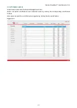
Страница 23: ...ol Click Outlet control form the Device Management menu Users can switch on off reboot each individual outlet by clicking the corresponding on off reboot buttons Also users can switch on or off all socket together by clicking the ALL on off button Figure 3 10 ...
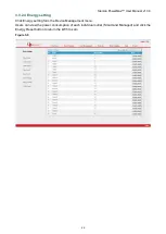
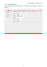
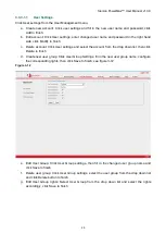
Страница 24: ...Siemon PowerMax User Manual v1 3 0 24 3 3 3 User Management Click User Management form the navigation bar to manage users user group and user access rights Figure 3 11 ...
Страница 25: ...account from the drop down list then click Delete to finish d Create new user group Click User Group Settings fill in the new user group name configure the corresponding rights then click Save to finish see figure 3 12 Figure 3 12 e Edit User Group Click User Group settings then fill in the changed user group name and click Save to finish f Delete user group Click User Group settings select the us...
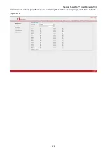
Страница 26: ...Siemon PowerMax User Manual v1 3 0 26 Administrators can assign different outlet access rights to different user groups click Save to finish Figure 3 13 ...
Страница 27: ...iemon PowerMax User Manual v1 3 0 27 3 3 4 Network Settings Click Network Settings from the navigation bar Figure 3 14 Note network settings include Network WIFI HTTP SSH FTP Modbus SNMP Telnet SMTP NTP ...
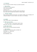
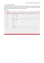
Страница 28: ...tomatic acquisition and click Save then restart the software device will assign an IP address automatically The device IP address can be viewed on the LCD display 3 3 4 2 WIFI Insert a wireless network card into the USB port ii WIFI Connection Setting Click Search Network to find all wireless networks nearby Enable WIFI select enable fill in SSID and password and save iii WIFI Network Setting Netw...
Страница 29: ...ll out the WIFI connection settings and save select automatic acquisition from the drop down list of WIFI network settings and save Then restart the device and system will acquire the IP address within the LAN The address can be viewed on the LCD display Figure 3 15 ...
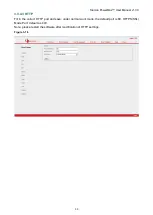
Страница 30: ...al v1 3 0 30 3 3 4 3 HTTP Fill in the correct HTTP port and save under normal work mode the default port is 80 HTTPS SSL Mode Port default as 443 Note please restart the software after modification of HTTP settings Figure 3 16 ...
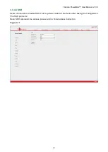
Страница 31: ...al v1 3 0 31 3 3 4 4 SSH Users can enable or disable SSH This requires a restart of the device after saving the configuration The SSH port is 22 Note SSH command line access please refer to Telnet access instruction Figure 3 17 ...
Страница 32: ... Manual v1 3 0 32 3 3 4 5 FTP Users can enable or disable FTP This requires a restart of the device after saving the configuration The FTP port is 21 Note Users can upgrade remotely by enabling the FTP service Figure 3 18 ...
Страница 33: ...200 38400 57600 115200 data bit 6 7 8 parity N A even number odd number stop bit 1 2 Note The Master unit collects data from the SER port please refer to the MODBUS protocol detail for reference 3 3 4 7 Sensor box The Modbus function is disabled when the sensor box functional mode is enabled This function is only for horizontal RPDU Figure 3 19 ...
Страница 34: ...d Write community is public and private Both strings can be changed if required Trap address 2 trap addresses can be set Fill in the trap address of SNMP management platform Trap information will be sent directly to the addresses SNMP server position records the server position information SNMP v3 settings Select Enable and fill in account password private key Note After configuring SNMP settings ...
Страница 35: ...Siemon PowerMax User Manual v1 3 0 35 3 3 4 9 Telnet Telnet select Enable or Disable and save Restart the software after modification Fill in Telnet account and password Telnet port is 23 Figure 3 21 ...
Страница 36: ...eters of SMTP service including SMTP account password SMTP server port and authentication mode After saving restart the software to take effect SMTP test fill in the receiver account click Test and then check the test receiver account If test email is received SMTP setting is successful if not reset the SMTP Figure 3 22 ...
Страница 37: ... NTM service and click Save Then restart the device Enable NTP fill in the NTP server and port select time zone and click Save Click Synchronization device will automatically update to the local system time according to the current time zone and date from the internet User defined setting Disable NTP first and then fill in the date and time Figure 3 23 ...
Страница 38: ...e will authenticate a user account from the Radius server Server address fill in the Radius server address Shared secret fill in the required public key of the Radius server Note please restart the software after configuration Then fill in the requested account and password of Radius server After authentication users can access the device Figure 3 24 ...
Страница 39: ...9 3 3 4 13 SYSLOG Fill in the SYSLOG server IP address Figure 3 25 Note SYSLOG contains system start service errors during operation and command error information After saving the SYSLOG server address restart the software to take effect ...
Страница 40: ...mon PowerMax User Manual v1 3 0 40 3 3 5 Data Graphing Select device to view information over the past 24 hours including total power kW current Ampere voltage average temperature and humidity Figure 3 26 ...
Страница 41: ...istoric data and energy data 3 3 6 1 Logs Record Shows the operation time log type user name and log details Memory capacity 100Mb To view the data Click Next or Previous to move page by page or Jump to go to a specific page Delete the logs Click Delete Logs The device will request confirmation click OK to delete all the logs Figure 3 27 ...
Страница 42: ...Max User Manual v1 3 0 42 3 3 6 2 History Data Select the date device and information type total power voltage power temperature and humidity you want to view and then click View to see the history data Figure 3 28 ...
Страница 43: ...x User Manual v1 3 0 43 3 3 6 3 Energy Record Select the device start and end date and click View The system will show the accumulated kWh value on each date and calculate the kWh value during that period Figure 3 29 ...
Страница 44: ...gs and network settings through batch download Users can upload all the backup information by using the upgrade tool Users can upgrade the software version through the Rootfs bin file provided by following the instructions in the upload software Note Please make sure the PDU is directly connected to the PC Do not power off disconnect the network or control the PDU during upgrading Restart the soft...
Страница 45: ...r to manage up to 5 devices To open the Telnet client Start Run command enter Telnet in the input box and click OK Enter the IP address Figure 3 31 Enter the username and password The Telnet interface will pop up Figure 3 32 3 4 1 STATUS command Input STATUS command to view the individual outlet status including current on off state Max and Min current value kW and kWh and the overall status inclu...
Страница 46: ...ex device mode 0 9 0 is master 1 4 is slave operation view the device information details as below operation Description Total For example Enter command line status 0 total 0 means the Master 1 4 means Slave 1 to Slave 4 total means the overall status the above figure shows input status 0 total sensor ...
Страница 47: ...aster unit 1 4 means the Slave units Output For example command line status 0 1 0 means the Master 1 4 means Slave 1 to Slave 4 1 means the status of first outlet the above figure will be displayed after input status 0 1 3 4 2 ON OFF command ON OFF command enables the user to switch on off the individual outlet or the complete device Command format ON OFF index operation ...
Страница 48: ...ax User Manual v1 3 0 48 Figure 3 34 index device mode 0 9 0 is master 1 4 is slave operation view device information operation Description ALL Command line on 0 all means to switch on all outlets of the Master unit ...
Страница 49: ... 4 3 Set command Set command enables setting of outlet current temperature and humidity minimum and maximum threshold IP address subnet mask gateway dns dns1 Command format set index operation Figure 3 35 index device mode 0 9 0 is master 1 4 is slave operation view device information details as below operation Description ...
Страница 50: ... 1 as a1 current Command line set 0 current1 min 0 max 12 means minimum current as 0 and maximum current as 12 for output 1 of Master unit temperature Command line set 0 temp1 min 0 max 60 means minimum temperature as 0 degree and maximum temperature 60 degree for temperature sensor 1 of master unit ...
Страница 51: ... 0 and maximum humidity as 90 for humidity sensor 1 of Master unit Tcurrent Command line set 0 Tcurrent1 Tmin 0 Tmax 16 means minimum current as 0A and maximum current as 16A for total current of phase A of Master unit network Command line set 0 ip 172 16 10 154 means Master network IP address as 172 16 10 154 ...
Страница 52: ...Siemon PowerMax User Manual v1 3 0 52 3 4 4 Network command Check network configuration information such as IP address subnet mask default gateway main DNS spare DNS Figure 3 36 ...
Страница 53: ... v1 3 0 53 3 4 5 Reboot Command Reboot command to restart device Figure 3 37 To exit the telnet interface and restart the device choose y and enter type n and press Enter to exit the telnet interface without restarting the device ...
Страница 54: ...Siemon PowerMax User Manual v1 3 0 54 3 4 6 RESET command To restore to factory settings Figure 3 38 ...
Страница 55: ...got IP address Check on the LCD screen the first page displays the IP address 4 2Failed to send email Check and confirm that the device is connected to network and the network is working normally Check DNS configuration and confirm whether it is successful Check and confirm POP SMTP sever is correct and the same as the sender mailbox sever Confirm SMTP port is correct 4 3Lost IP Press and hold the...
Страница 56: ...C320 C13 C19 Socket quantity Monitored Series 8 16 24 36way Smart Series 8 16 24way Switched Series 8 16 24way Managed Series 8 16 24way Output voltage 110 220VAC 50 60HZ Output current 16A 32A 3 16A 3 32A 3 Control ports Net port 1xRJ45 port Daisy chain port 2xRJ45 port Software update port 1x RJ45 port Temperature humidity port Max 2xRJ11 port can add more Smoke sensor port Max 1xRJ11 port optio...
Страница 57: ...emperature humidity sensor Smoke sensor Door sensor Water logging sensor 11 Environment Working Environment Temperature 10 45 Relative humidity 5 95 Storage Environment Temperature 20 70 Relative humidity 5 95 12 ROHS Compliance 6 Warranty and Service Siemon warranties the PDU to be free from any defects material and workmanship for a period of two years from the date of purchase Siemon s obligati...
Страница 58: ...nstall this device in a wet location D Never install wiring during a lightning storm Lors de l installation respectez les consignes de sécuritésuivantes A Utiliser avec prudence lors de l installation ou de la modification circuits de télécommunications B Ne jamais toucher les bornes de fil métallique non isolés sauf si le circuit a étédébranché C Ne jamais installer cet appareil dans un endroit h...