GAMMA
instabus
Technical Specification
March 2010
Colour touch panel UP 588/13
5WG1 588-2AB13
Colour touch panel UP 588/23
5WG1 588-2AB23
Accessories:
Design frame aluminium
5WG1 588-8AB12
Design frame stainless steel design
5WG1 588-8AB13
Design frame glass black
5WG1 588-8AB14
Design frame glass white
5WG1 588-8AB15
flush-type box
5WG1 588-8EB01
Siemens AG
UP 588, 6 pages
Technical Manual
Industry Sector, Building Technologies
Low Voltage Distribution
© Siemens AG 2010
Update: http://www.siemens.com/gamma
PO Box 10 09 53, D-93009 Regensburg
Subject to change without further notice
2.3.1.7/5
into the device. At the same time, take note of the
direction for mounting the frame. Finally, the
passepartout blind
5
are plugged on to the display and
thus held by the frame. The mounting direction must
also be observed when mounting the passepartout blind.
It is to be plugged in such that all elements of the display
frame are covered completely.
V
Caution:
Do not press directly on the display!
After mounting is completed, the device can be used (for
programming, see the application program description).
Please note the device can only be started after the
power supply and the bus voltage have been switched
on and this may take up to 1 minute.
Dismantling / exchanging the design frame
-
First of all switch off the power supply
-
The passepartout blind must be removed initially to
dismount the device or exchange the frame.
V
Caution:
Do not press directly on the display!
After removing the passepartout blind, the design frame
can be exchanged or the device dismounted completely.
Disconnecting the power supply (figure 4 "B")
-
To dismount the power supply terminal (C4), this must
be pulled downwards over the detente and out of the
slot. The removal can be made easier by lifting the
power supply connection terminal (C4) slightly with a
flat-bladed screwdriver. To do this, push the blade of
the screwdriver into the centre of the terminal detente
between the power supply connection terminal (C4)
and the base of the slot.
Removing the bus terminal (figure 4 "A")
-
The bus terminal (C3) is in the left slot. It consists of
two parts (C3.2 and C3.3), each with four terminal
contacts. You must take care that both test sockets
(C3.1) are not damaged, either with the bus conductor
(accidental attempt to plug in) or with the screwdriver
(e.g. when trying to remove the bus terminal).
-
Push the screwdriver carefully into the wire connection
slot of the grey part of the bus terminal (C3.3) and
then pull the bus terminal (C3) out of the device. When
pulling out the red part of the bus terminal, the grey
part remains plugged in.
Notice:
Do not lever the bus terminal outwards from
below! Danger of short circuit!
Disconnecting the bus terminal (figure 4 "A")
Pull off the bus terminal (C3) and pull out its conductor
(C3.4) by turning it alternately backwards and forwards.
Resetting the device if there is an error
You reset the touch panel in the event of an error with
the reset button. The reset button
F
(see figure 5) is
accessible after dismounting the design frame (see
above). This is done with the special tool. Should the
display fail in rare cases owing to a fault in the software
or during the loading process, tap the reset button. The
device then restarts within a few seconds and the design
frame can be remounted as described above. If the
device will not start, despite a reset, contact the
manufacturer.
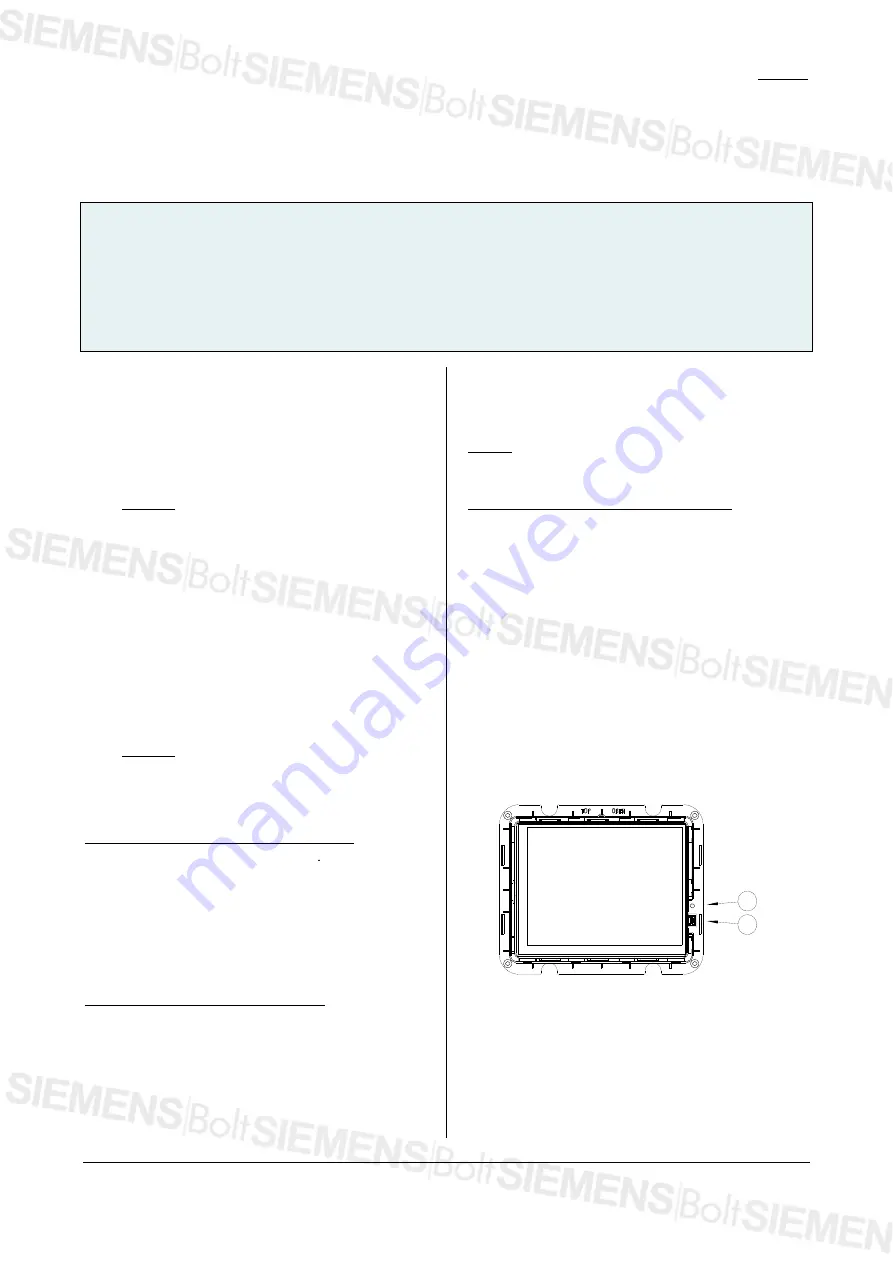
E
F
Figure 5:
Reset button and USB port
Extended programming via the front USB port
Pictures and symbols to order (see the user manual for
this) are transferred via the front mini-USB socket
E
(see
figure 5)
.
The USB socket is accessible after dismounting
the design frame (see above). Connect the display to any


