background image

18

TPS4 Surge Protection Devices | 

Installation Guide / User Manual

19

Installation Guide / User Manual

 | TPS4 Surge Protection Devices

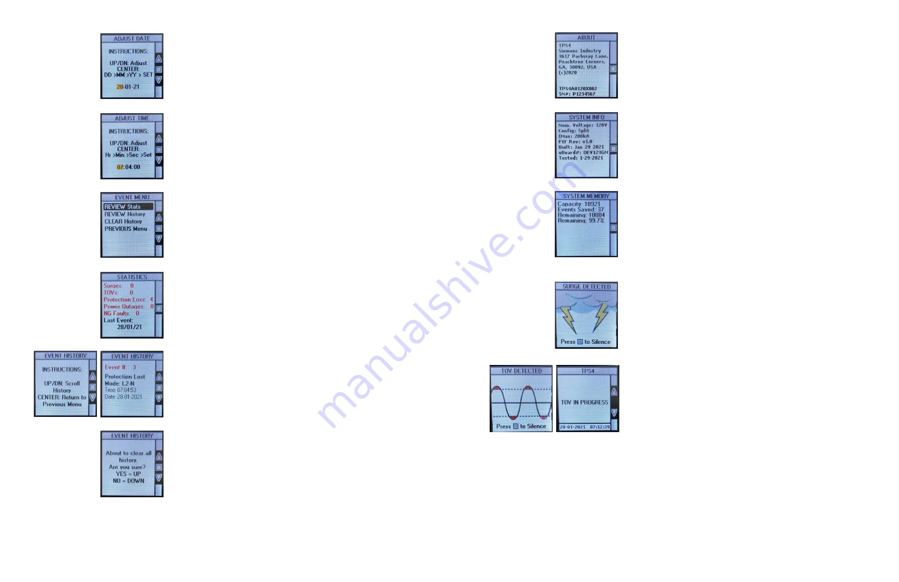
Event History Screen

The Event History Screen will allow you to review each event the SPD has  
on record. Use the UP/DOWN buttons to scroll through the event log.

Pressing the CENTER button will return you to the Event Menu Screen.

Clear Event History Screen

The Clear Event History Screen will allow you to clear the SPD’s event log. 
Pressing the UP button (YES) will clear the event log. Pressing the DOWN button 
(NO) will keep the current event log intact. Either operation will return you to 
the Event History Screen.

Adjust Date Screen

The Adjust Date Screen will allow you to set the date of the SPD. Use the UP/
DOWN buttons to adjust the value in the selected field until you have the correct 
value. Pressing the CENTER button will advance the cursor to the next date field. 
Once the “Year” has been set, pressing the CENTER button will finalize your 
changes and save them to the SPD memory. You will automatically be brought 
back to the Setup Menu.

Adjust Time Screen

The Adjust Time Screen will allow you to set the time of the SPD. Use the UP/
DOWN buttons to adjust the value in the selected field until you have the correct 
value. Pressing the CENTER button will advance the cursor to the next time field. 
Once the “Seconds” have been set, pressing the CENTER button will finalize your 
changes and save them to the SPD memory. You will automatically be brought 
back to the Setup Menu.

Event Menu Screen

The Event Menu Screen will allow you to view the SPD’s statistics and event 
history. You are also able to clear the history if need be. Use the UP/DOWN 
buttons to select which operation to do. Pressing the CENTER button will 
advance you to the screen you have selected.

Statistics Screen

The Statistics Screen shows the number of events that the SPD has experienced. 
The total number of each event type will be shown here. The date of the last 
recorded event will also be shown here. Unlike the Event Log, this data cannot 
be cleared from memory. Pressing the left button (BACK) will return you to the 
Main Screen.

About Screen

The About Screen displays the manufacturer’s information, the model number 
and the serial numberfor this specific SPD. Pressing the CENTER button will 
return you to the Main Menu Screen.

System Info Screen

The System Screen displays the important electrical information for this system. 
This includes the nominal operating voltage, System configuration (ie. Wye, 
Delta, Single Phase) and maximum current rating for each mode of the SPD. The 
processor serial number, firmware edition, build and test dates are also shown 
on this page. Pressing the CENTER button will return you to the Main Menu 
Screen.

System Memory Screen

The System Memory Screen displays the current state of the electronic  
memory for this system. This includes the nominal operating voltage, System 
configuration (ie. Wye, Delta, Single Phase) and maximum current rating for 
each mode of the SPD. The processor serial number, firmware edition, build and 
test dates are also shown on this page. Pressing the CENTER button will return 
you to the Main Menu Screen.

Surge Event Screen

When the SPD detects a surge event this animation will be shown. It will remain 
on screen until acknowledged by an operator. Any subsequent events that occur 
while the Surge event animation is on screen will be registered and queued for 
acknowledgment. Along with displaying the Surge animation, the Audio alarm 
will sound. Pressing the CENTER button will acknowledge the event and clear  
the alarm state. The Main Screen will be showing the details for the surge.

System Event Alarms

Temporary Over Voltage Event

When the SPD detects a Temporary Over Voltage Event (TOV) this animation  
will be shown. It will remain on screen until acknowledged by an operator. Any 
subsequent events that occur while the TOV event animation is on screen will  
be registered and queued for acknowledgment. Along with displaying the  
TOV animation, the Audio alarm will sound. Pressing the CENTER button will 
acknowledge the event and clear the alarm state. The Main Screen will be 
showing the details for the TOV.

The SPD may be exposed to a TOV for several minutes. On rare occasions a TOV 
can exist for hours. The TOV animation will be displayed as soon as a TOV has 
been detected. If an operator is able to acknowledge the event while a TOV 
condition still exists, the screen below will be displayed.

Содержание TPS4 Series

Страница 1: ...usa siemens com spd Installation Guide User Manual Surge Protection Devices TPS4 Series Products for Panelboards Switchboards and other Apparatus ...

Страница 2: ...he SPD and system must be verified before energizing the SPD Failure to follow these guidelines can lead to abnormally high voltages at the SPD This may cause the SPD to fail The warranty is voided if the SPD is incorrectly installed and or if the neutral conductor in the service entrance equipment or downstream of separately derived systems is not bonded to ground in accordance with the NEC Do No...

Страница 3: ...ally the company is not responsible for incidental or consequential damages resulting from any defect in any product or component thereof The sales contract contains the entire obligation of Siemens This instruction manual shall not become part of or modify any prior existing agreement commitment or relationship Unpacking Preliminary Inspection Inspect the entire shipping container for damage or s...

Страница 4: ...e and use gentle radius on any bends Do not kink wire Prevent wire from encroaching breaker locations Neutral Connection is not applicable on Delta systems Step 6 Torque all connections to the values as specified on the installation and maintenance instruction label affixed to the rear of the dead front Table 3 Content for Installation in Lighting Panelboards Revised P1 7 6 TPS4 Surge Protection D...

Страница 5: ...PD units in the field re use the hardware originally installed and use the table as a guide for proper torque values NOTE For wired installations see details in the previous section only 2 tabs for single phase modules Torque Note For Item 10 see Bus Connection Tightening Torque values on label 15 A 1043 01 inside panel board W Option Instruction The W option includes repositioned phase connection...

Страница 6: ...abnormally high voltages at the SPD This may cause the SPD to fail The warranty is voided if the SPD is incorrectly installed and or if the neutral conductor in the service entrance equipment or downstream of separately derived systems is not bonded to ground in accordance with the NEC Do Not Hi Pot Test SPDs The TPS4 unit needs to be fully disconnected during Hi Pot testing Failure to disconnect ...

Страница 7: ...ne wire compression lugs to phase connections on TPS4 module Torque to 45 in lbs Step 10 If present reattach neutral wire to mechanical lug on side of TPS4 module Torque to 35 in lbs Step 11 Turn the internal disconnect back to the ON position Step 12 Close all doors before reenergizing The following instructions are for the replacement of Siemens TPS4 SPD module in Siemens TPS4 05 unit 12 TPS4 Su...

Страница 8: ...tep 13 Close equipment doors before reenergizing The following instructions are for the replacement of Siemens TPS4 SPD module in Siemens TPS4 06 unit 14 TPS4 Surge Protection Devices Installation Guide User Manual 15 Installation Guide User Manual TPS4 Surge Protection Devices Figure 1 SPLIT 2 Hots 1 Neu 1 Grnd Figure 2 WYE 3 Hots 1 Neu 1 Grnd Figure 3 HI LEG DELTA B High 3 Hots B HIGH 1 Neu 1 Gr...

Страница 9: ...tors one per phase Green is good Extinguished green LED indicates loss of protection Every suppression element in this SPD is monitored N G suppression element monitoring is logic connected to Phase A Service LED red LED illuminates in the event of problems This indicator is logic connected to the Phase LEDs Should a Phase LED go out the Service LED will illuminate and the Audible Alarm will sound...

Страница 10: ...in Screen About Screen The About Screen displays the manufacturer s information the model number and the serial numberfor this specific SPD Pressing the CENTER button will return you to the Main Menu Screen System Info Screen The System Screen displays the important electrical information for this system This includes the nominal operating voltage System configuration ie Wye Delta Single Phase and...

Страница 11: ... the SPD If not corrected SPD problems will reoccur Tip Visually confirm N G bonding Be aware that a voltmeter measuring N G can be misleading For example N G voltage could read 0V because neutral and ground are at the same potential purely by happenstance not because they are bonded Visually confirm bonding Tip Experience indicates that regulation challenged generators can cause Sustained Overvol...

Страница 12: ...22 TPS4 Surge Protection Devices Installation Guide User Manual Notes ...

Страница 13: ...d does not constitute a performance guarantee for any projects Actual results are dependent on variable conditions Accordingly Siemens does not make representations warranties or assurances as to the accuracy currency or completeness of the content contained herein If requested we will provide specific technical data or specifications with respect to any customer s particular applications Our comp...

Отзывы: