
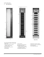
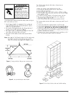
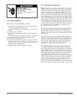


3.4 Mounting
Motor control centers may be mounted by many different fas-
tening systems including true drop in, cast in place, powder
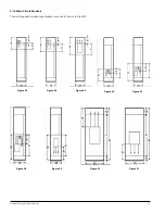
actuated, or threaded insert fasteners. See Figure 6 for anchor
bolt locations. The bolt pattern is dependent on frame width,
depth, location in the line-up. Refer to the structure mounting
detail included on the L1 layout drawing lead sheet. The coor-
dination between bolts and the MCC should be verified prior to
attempting installation. Expandable inserts in predrilled holes
or embedded .L. bolts are recommended. Wooden
plugs driven into holes in masonry or concrete are not recom-
mended for anchoring inserts and should never be used. The
bolt size must be 1/2".
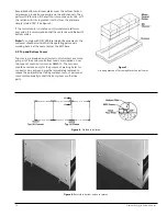
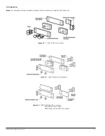
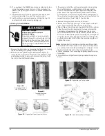
Grouting the sill channels is another method of fastening. This
method requires the foundation to be grooved as shown to
accept the sill channels. See Figure 7 for details.
Welding the steel base or sill channels to a steel floor plate is
an alternate mounting method. See Figure 6 for details.
Note:
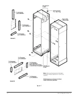
Rear top plate can be used for conduit on 20"
deep MCC. Cables can then be run from rear to
front through optional wireway holes to connect
units.
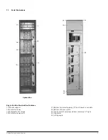
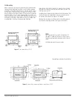
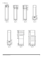
All Dimensions are Shown in Inches.
Shaded Area Indicates Conduit Entry
Figure 5
-
Top Conduit Entry: 15” 20”
Figure 6
-
Anchor Bolt Location and Bottom Conduit Entry: 15” 20”
Siemens Energy & Automation, Inc.
11
Содержание TIASTAR
Страница 1: ...TIASTAR Motor Control Center Instruction Guide SFIS 70060 0509 May 2009 ...
Страница 14: ...Figure 11 Siemens Energy Automation Inc 14 ...
Страница 17: ...Siemens Energy Automation Inc 17 Figure 15 ...
Страница 43: ...Siemens Energy Automation Inc 43 ...
Страница 44: ...Siemens Energy Automation Inc www sea siemens com Publication No SFIS 70060 0509 Printed in the USA ...