


TC65 Terminal Hardware Interface Description
Confidential / Released
s
TC65 Terminal_HD_V02.000b
Page 39 of 65
2007-02-19
3.10.4 SPI
Interface
The SPI interface is located on the IO interface connector of the TC65 Terminal. The SPI
(Serial Peripheral Interface) is a synchronous serial interface for controlling and data transfer
between the TC65 Terminal and a connected application. Only one application can be
connected to the Terminal’s SPI.
The SPI consists of four lines. These are the two data lines SPIDI/SPIDO, the clock line
SPICLK and the chip select line SPICS.
The TC65 Terminal acts as a single master device, e.g. the clock SPICLK is driven by the
TC65 Terminal. Whenever the SPICS pin is in a low state, the SPI bus is activated and data
can be transferred from the Terminal and vice versa. The SPI interface uses two
independent lines for data input (SPIDI) and data output (SPIDO). The interface supports
transmission rates up to 6.5Mbit/s. Transfer rates >1.083Mbps and a length of the cable
>150mm are not recommended.
The SPI interface is only available if the pins 1 and 2 of the IO interface connector are not
used as I
2
C interface.
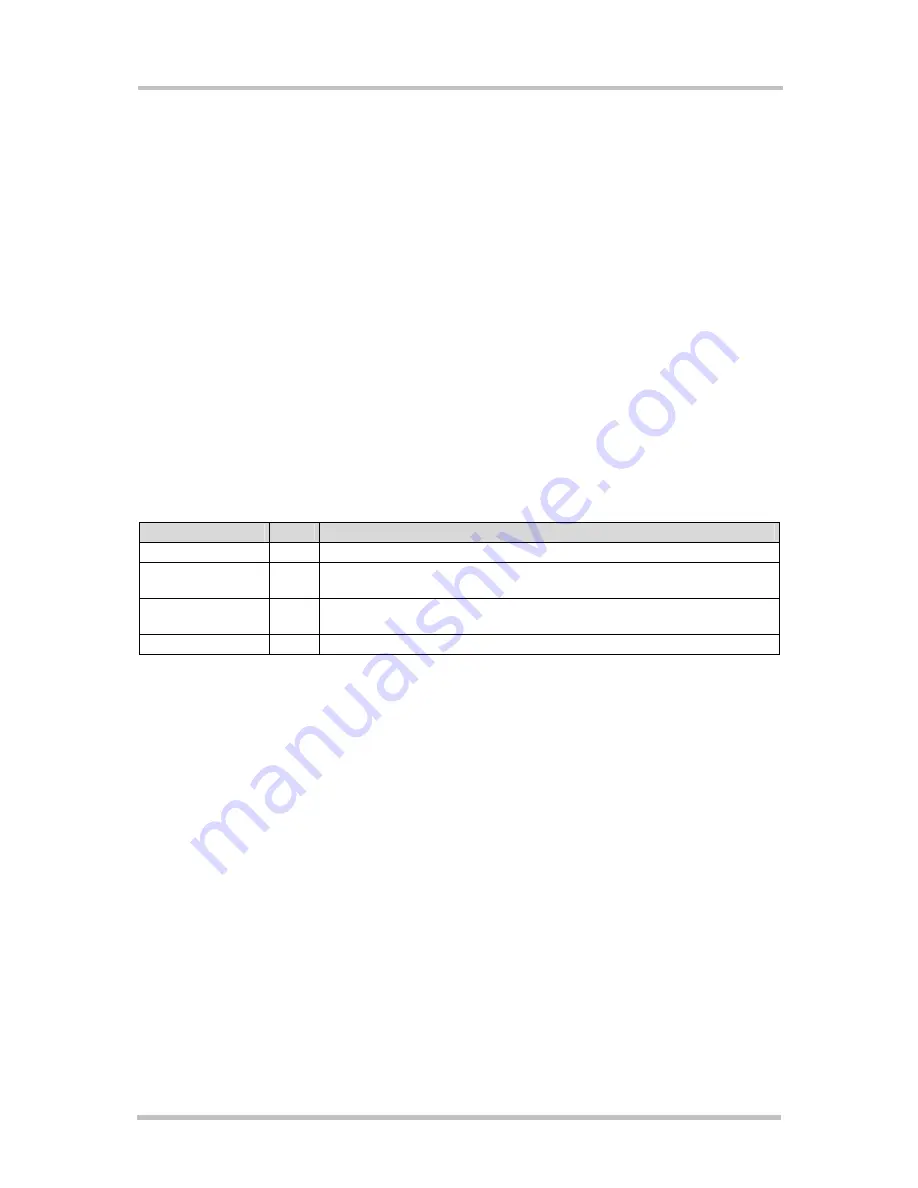
Table 15: SPI interface – signal description
Signal name
Pin
Description
SPICS
13
Chip select – selects and activates the external device via a low signal.
SPIDI
14
Data in – serial data input line (from the external device to the TC65
Terminal)
I2CDAT_SPIDO
1
Data out – serial data output line (from the TC65 Terminal to the
external device)
I2CCLK_SPICLK
2
Serial clock line
The SPI Interface can be used in 4 different modes. Figure 12 shows the characteristics of
these modes.