background image

4/8 

Siemens Building Technologies 

Electrical Actuators 

CA1N4895en 

HVAC Products 


08.03.2004 

Notes 

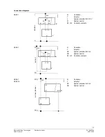
The actuators must be electrically connected in accordance with local regulations (refer 
to «Connection diagrams»). 

Regulations and requirements to ensure the safety of people and property must 
be observed at all times! 

The permissible temperatures must be observed (refer to «Technical data»). 
 
Mounting Instructions 74 319 0260 0 are enclosed with each pack. 
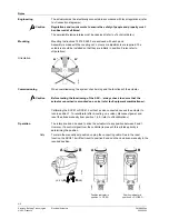
Assembly is made with the coupling nut; no tools or adjustments are required. The 
actuators should be installed so that they are initially in position 0 (also refer to 
«Operation»). 
 

90°

90°

48

99

Z03


When commissioning the system, check wiring and the functions of the actuator. 


Before testing the functioning of the SSC..., always check to ensure that the 
actuator concerned is mounted on a valve (refer to «Equipment combinations»). 


Calibrating the SSC61 or SSC61.5 without a valve connected causes the actuator to 
lock in position 1. To recalibrate (after mounting on a valve), disconnect power and 
reset the stroke manually from position 1 to 0 (refer to «Recalibration»).  
 
The rotary knob can be used to drive the actuator into any position between 0 and 1. 
However, if a control signal from the controller is present, this will take priority in 
determining the position. 

To retain the manually set position, unplug the connecting cable. Due to the reset 
function, the SSC61.5 will first travel to position 0 and can then be driven manually to the 
required position. 
 

B

A

(Y2)

(Y, Y1)

 A

48

9

5Z04

A

4895

Z

0

5

0

1


Position indicator in 

position 1 = OPEN 

B

489

5Z

06

0

1


Position indicator in 

position 0 = CLOSED 

Engineering 

  Caution 

Mounting 

Orientation 

Commissioning 

  Caution 

Operation 

Note 

Содержание SSC31

Страница 1: ...n Nominal force 300 N Automatic identification of valve stroke Direct mounting with coupling nut no tools required Cable connection via screw terminals Manual override indication of position and direction of travel Parallel connection of multiple actuators Special UL listed versions Use For operation of Siemens valves of the VVP45 VXP45 and VMP45 range for water side control of hot water and cooli...

Страница 2: ...ombinations Type reference Type of valve kvs m 3 h PN class Data Sheet VVP45 2 port valves 0 25 25 PN16 N4845 VXP45 3 port valves VMP45 3 port valves with T bypass 0 25 4 VVG45 1 2 port valves 0 63 25 VXG45 1 3 port valves X3i 1 3 port valves 0 7 14 Retrofitting to former L G valves 1 With ASK30 mounting kit Function mechanical design When the actuator is driven by a 3 position or DC 0 10 V contro...

Страница 3: ...ves the valve to the mechanical end stops and stores the associated positions permanently in the form of electronic values The positioning signal is only active on completion of this calibration process Calibration takes about 60 seconds The SSC61 5 only performs auto calibration when the charging process of 180 seconds is completed If the calibrated actuator is used with some other valve e g a re...

Страница 4: ... of the SSC always check to ensure that the actuator concerned is mounted on a valve refer to Equipment combinations Calibrating the SSC61 or SSC61 5 without a valve connected causes the actuator to lock in position 1 To recalibrate after mounting on a valve disconnect power and reset the stroke manually from position 1 to 0 refer to Recalibration The rotary knob can be used to drive the actuator ...

Страница 5: ... Products Technical data SSC31 SSC81 SSC61 SSC61 5 AC 24 V or DC 24 V Power supply Rated voltage Voltage tolerance AC 230 V 15 AC 24 V 20 20 25 Rated frequency 50 60 Hz Max power consumption 6 VA 0 8 VA 2 VA 2 VA 1 Fuse for incoming cable fast 2 A Control Control signal 3 position DC 0 10 V Input impedance for DC 0 10 V 100 kOhm Positioning accuracy for DC 0 10 V 2 of nominal stroke Parallel opera...

Страница 6: ...utput is sufficient General ambient conditions Operation IEC 721 3 3 Transport IEC 721 3 2 Storage IEC 721 3 1 Environmental conditions class 3K3 class 2K3 class 1K3 Temperature 5 50 C 25 70 C 25 70 C Humidity 5 95 r h 95 r h 5 95 r h Connection terminals All actuators must be electrically connected and installed in accordance with local safety regulations Y2 Y1 N 4895Z06 Control signal CLOSE AC 2...

Страница 7: ...l 4864A01 L N L N AC 230 V N Y2 Y1 2AF N Y1 Y2 Q1 Q2 Y Q1 Q2 Controller contacts N Controller Y Actuator SP System potential AC 24 V SN System neutral 4864A02 Y1 G G0 SP SN AC 24 V G Y2 Y1 Y2 N Q1 Q2 2AF Y Q1 Q2 Controller contacts N Controller Y Actuator SP System potential AC 24 V 4864A03 Y N Y G0 G Y G0 SP SN AC 24 V DC 24 V G 2AF SN System neutral SSC31 SSC81 SSC61 SSC61 5 ...

Страница 8: ...ns Building Technologies Electrical Actuators CA1N4895en HVAC Products 08 03 2004 Dimensions All dimensions in mm 48 110 8 89 2 21 6 115 1 132 5 4895Z08 G 2004 Siemens Building Technologies AG Subject to change ...

Отзывы: