SIWAREX WP231
Manual, 07/2014, A5E31238908A-02
29
Connection
6
6.1
Overview
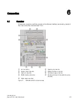
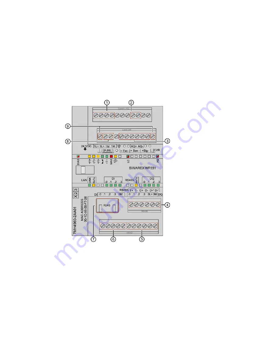
All external connections (with the exception of the Ethernet interface) are made by means of
the screw connectors (terminal block 1 to 4).
①
24 V connection
⑥
Digital input connection
②
Analog output connection
⑦
Ethernet interface connection
③
Load cell connection
⑧
Calibration bridge connection
④
RS485 interface connection
⑨
Mounting terminals for the calibration protec-
tion plate
⑤
Digital output connection
Figure 6-1
SIWAREX WP231 connection areas
Содержание SIWAREX WP231
Страница 16: ...Safety notes 2 1 General safety instructions SIWAREX WP231 16 Manual 07 2014 A5E31238908A 02 ...
Страница 24: ...Application planning 4 2 Parameter assignment options SIWAREX WP231 24 Manual 07 2014 A5E31238908A 02 ...
Страница 108: ...Scale parameters and functions 8 15 DR 15 tare settings SIWAREX WP231 108 Manual 07 2014 A5E31238908A 02 ...
Страница 131: ...Scale parameters and functions 8 26 DR 48 date and time 2 for Modbus SIWAREX WP231 Manual 07 2014 A5E31238908A 02 131 ...
Страница 132: ......
Страница 174: ...Technical data 13 3 Approvals SIWAREX WP231 174 Manual 07 2014 A5E31238908A 02 ...
Страница 180: ...List of abbreviations SIWAREX WP231 180 Manual 07 2014 A5E31238908A 02 ...
Страница 182: ...Index SIWAREX WP231 182 Manual 07 2014 A5E31238908A 02 ...

