Description, device design, dimension drawing
2.5 Buttons and selector switches
SITOP SEL1200-1400
16
Manual, 06.2019, A5E46496083-1-76
2.5
Buttons and selector switches
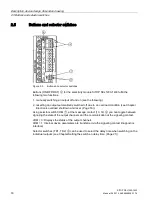
Figure 2-5
Buttons and selector switches
Buttons (ON/OFF/RST)
⑥
for the selectivity module SITOP SEL1200-1400 fulfill the
following two functions:
1.
manually switching an output off and on (see the following).
2.
resetting an output automatically switched off due to an overload condition (see Chapter
Electronic overload shutdown and reset (Page 18)).
Using selector switch COM
⑦
, at the message contact (13, 14)
④
you can toggle between
signaling the state of the output channels and the communication at the signaling contact.
COM = 0: Displays the status of the output channels
COM = 1: Internal device parameters are transferred via the signaling contact (diagnostics
interface)
Selector switches (TD1, TD2)
⑧
can be used to select the delay time when switching on the
individual outputs (see Chapter Setting the switch-on delay time (Page 21)).
Содержание SITOP SEL1200
Страница 8: ...Safety instructions SITOP SEL1200 1400 8 Manual 06 2019 A5E46496083 1 76 ...
Страница 26: ...Mounting removal SITOP SEL1200 1400 26 Manual 06 2019 A5E46496083 1 76 ...
Страница 36: ...Installation 5 2 Connection at the output SITOP SEL1200 1400 36 Manual 06 2019 A5E46496083 1 76 ...
Страница 46: ...Safety approvals EMC 7 3 EMC SITOP SEL1200 1400 46 Manual 06 2019 A5E46496083 1 76 ...
Страница 48: ...Ambient conditions SITOP SEL1200 1400 48 Manual 06 2019 A5E46496083 1 76 ...
Страница 50: ...Environment SITOP SEL1200 1400 50 Manual 06 2019 A5E46496083 1 76 ...


