background image


Description, device design, dimension drawing 


2.7 Setting the switch-on delay time 

SITOP SEL1200-1400 
Manual, 06.2019, A5E46496083-1-76 

21


2.7


Setting the switch-on delay time 

For specific loads, it can make sense to sequentially switch-on the outputs in order to reduce 

the peak inrush currents, and therefore the load on the power supply. To achieve this, the 

individual outputs of the selectivity module can be switched-in with a time delay between one 

another in a fixed sequence (output 1 ⇒ 2 ⇒ 3 ⇒ 4 ⇒ 5 ⇒ 6 ⇒ 7 ⇒ 8). The delay time set 

between the individual outputs is the same for all of the outputs. The delivery condition is 

load-dependent switch on. 

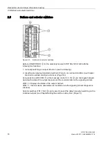
Setting the sequential switch-on delay 


Figure 2-8 

Selector switch 

The switch-on delay time is set at selector switches TD1 and TD2 

. When delivered, DIP 

switches "TD1" and "TD2" are in the "0" position (load-dependent switch on delay). 

Procedure when setting the delay time: 
With the selectivity module in a no-voltage condition, set DIP switches "TD1" and "TD2" to 

the required delay time. 


Outputs switched on depending on the load: The next output is switched on as soon as the 

previous output has run-up (at the earliest, after 5 ms). 


25 ms delay between the outputs being switched on 


200 ms delay between the outputs being switched on 


500 ms delay between the outputs being switched on 

The next time that the selectivity module powers up, the outputs are sequentially switched on 

corresponding to the selected delay time. 

Содержание SITOP SEL1200

Страница 1: ...TOP SEL1400 8 x 10 A 6EP4438 7EB00 3DX0 06 2019 A5E46496083 1 76 Overview Safety instructions 1 Description device design dimension drawing 2 Mounting removal 3 Mounting position mounting clearances 4 Installation 5 Technical data 6 Safety approvals EMC 7 Ambient conditions 8 Environment 9 Service Support 10 ...

Страница 2: ... by personnel qualified for the specific task in accordance with the relevant documentation in particular its warning notices and safety instructions Qualified personnel are those who based on their training and experience are capable of identifying risks and avoiding potential hazards when working with these products systems Proper use of Siemens products Note the following WARNING Siemens produc...

Страница 3: ...ffer a voltage free period of 10 ms At the time of shutdown the current cannot be briefly limited and as a consequence brief voltage dips below 20 V are possible SEL1400 is designed for demanding applications and does not permit voltage dips below 20 V for any period of time This is also suitable for loads consumers that do not comply with the PLC standard The key benefits of the product include A...

Страница 4: ...rrent Narrow design Push in terminals Ordering data The following device options are available Selectivity modules Type Order number SITOP SEL1200 8 10 A 24 V DC input Number of outputs 8 Setting range of the response threshold 2 10 A with group signaling contact 6EP4438 7FB00 3DX0 SITOP SEL1400 8 10 A 24 V DC input Number of outputs 8 Setting range of the response threshold 2 10 A with group sign...

Страница 5: ...7 Setting the switch on delay time 21 2 8 Block diagram 22 2 9 Dimensions and weight 23 3 Mounting removal 25 4 Mounting position mounting clearances 27 4 1 Standard mounting position 27 4 2 Other mounting positions 29 4 2 1 SEL1200 8 x 10 A 6EP4438 7FB00 3DX0 29 4 2 2 SEL1400 8 x 10 A 6EP4438 7EB00 3DX0 31 5 Installation 33 5 1 Connection at the input 33 5 2 Connection at the output 35 6 Technica...

Страница 6: ...Table of contents SITOP SEL1200 1400 6 Manual 06 2019 A5E46496083 1 76 7 Safety approvals EMC 43 7 1 Safety 43 7 2 Approvals 44 7 3 EMC 45 8 Ambient conditions 47 9 Environment 49 10 Service Support 51 ...

Страница 7: ...l injury as well as extensive property damage Only appropriately qualified personnel may work on or in the vicinity of this equipment Perfect safe and reliable operation of this equipment is dependent on proper transportation storage installation and mounting Before installation or maintenance work can begin the system s main switch must be switched off and measures taken to prevent it being switc...

Страница 8: ...Safety instructions SITOP SEL1200 1400 8 Manual 06 2019 A5E46496083 1 76 ...

Страница 9: ...rrent can be individually set for each output using a potentiometer When the set response threshold is exceeded the output is automatically switched off according to a defined switch off characteristic and can be switched on again after a wait time using a pushbutton ON OFF RST or remote reset RST The status of the output is displayed using a multi color LED for each output The status of the outpu...

Страница 10: ...rnal supply 24 V DC outputs Group signaling contact 13 14 not assigned NF remote reset RST Potentiometer for each output ON OFF RST pushbutton and indicator light for each output Selector switch for diagnostic interface COM Selector switch for switch in delay time definition TD1 TD2 Mounting rail slider Natural convection Clearance above below Figure 2 1 Design ...

Страница 11: ...tatus displays and signaling Page 13 The remote reset RST input is used to reset outputs that have automatically been shut down function see Chapter Status displays and signaling Page 13 Connections and terminal designations 24 V DC input 2 spring loaded terminals 0 V connection for the internal supply 2 spring loaded terminals 24 V DC output 1 8 one spring loaded terminal each Group signaling con...

Страница 12: ...ront of the device is used to set the response threshold of the output current When delivered the maximum possible response threshold is set Figure 2 3 Potentiometer Note It is only permissible to use an insulated screwdriver when actuating the potentiometer For information on actuating the potentiometer screwdriver torque see Figure 2 2 Terminal data Page 11 ...

Страница 13: ...ltage Remote reset RST non isolated 24 V DC input Signal level High for 15 V Indicator light and pushbutton ON OFF RST for each output Three color LED rot green and orange Selector switch for diagnostic interface COM Switchover between signaling the status of the output channels and communica tion at the signaling contact Figure 2 4 Status displays and signaling The operating state of the outputs ...

Страница 14: ...witched on again after a typical wait time of 20 s The wait time still to elapse is saved when switching off the device and is reactivated after the device has been switched on again Flashes red Output ready to be reset after an automatic switch off by actuating the ON OFF RST or remote reset RST effective for all outputs that have been automatically switched off all LEDs indi vidually flash red O...

Страница 15: ...tional information about the data transfer COM 1 is provided in the documents Diagnostics interface https support industry siemens com cs ww en view 109767425 Faceplates and communication blocks https support industry siemens com cs ww en view 109763709 See also SITOP http www siemens com sitop Support https support industry siemens com ...

Страница 16: ...ut automatically switched off due to an overload condition see Chapter Electronic overload shutdown and reset Page 18 Using selector switch COM at the message contact 13 14 you can toggle between signaling the state of the output channels and the communication at the signaling contact COM 0 Displays the status of the output channels COM 1 Internal device parameters are transferred via the signalin...

Страница 17: ... flashes orange output has been manually switched off Switching on an output For outputs that have been manually switched off LED of the particular output is lit orange You can switch on the output by pressing the assigned button ON OFF RST The LED is then lit green output is switched on Note An output that has been manually switched off can only be manually switched on again by manually pressing ...

Страница 18: ...50 a higher current is briefly permitted afterwards it is shut down corresponding to the Shutdown characteristic diagram The following applies for the SEL1400 In the range 150 of the selected current response threshold the current is limited to 150 typically after 10 ms to 100 ms the output is electronically shut down LED of the output is lit red An output current is continuously permissible up to...

Страница 19: ...oad condition This is signaled using the LED 1 8 of the particular output LED Meaning handling Lit red Electronic shutdown as a result of an overload wait time until a reset is possible approx 20 seconds Flashes red Output ready for a reset press the button to switch on the output again Lit green The reset was carried out the output was switched on again Procedure to reset an electronic shutdown 1...

Страница 20: ...the remote reset signal is evaluated i e for an additional remote reset signal initially a voltage level of 13 V must be fallen below Using a remote reset signal at terminal RST all outputs that were shut down electronically due to an overload are again reset Prerequisite The output is ready to be reset i e the electronic overload shutdown occurred longer than 20 s ago LED of the output flashes re...

Страница 21: ...ependent switch on Setting the sequential switch on delay Figure 2 8 Selector switch The switch on delay time is set at selector switches TD1 and TD2 When delivered DIP switches TD1 and TD2 are in the 0 position load dependent switch on delay Procedure when setting the delay time With the selectivity module in a no voltage condition set DIP switches TD1 and TD2 to the required delay time Outputs s...

Страница 22: ...Description device design dimension drawing 2 8 Block diagram SITOP SEL1200 1400 22 Manual 06 2019 A5E46496083 1 76 2 8 Block diagram Figure 2 9 Block diagram ...

Страница 23: ...imensions and weight SITOP SEL1200 1400 Manual 06 2019 A5E46496083 1 76 23 2 9 Dimensions and weight Figure 2 10 Dimension drawings 6EP4438 7FB00 3DX0 6EP4438 7EB00 3DX0 Dimensions W H D in mm 45 135 125 45 135 125 Weight Approx 0 30 kg Approx 0 50 kg ...

Страница 24: ...Description device design dimension drawing 2 9 Dimensions and weight SITOP SEL1200 1400 24 Manual 06 2019 A5E46496083 1 76 ...

Страница 25: ...ils see Chapter Mechanical system Page 41 Mounting To mount the device position it with the mounting rail guide at the upper edge of the standard mounting rail and press down to lock it into place If this is too difficult simultaneously press the slider as described under Removal Removal To remove pull up the slider using a screwdriver and disengage the device at the bottom edge of the standard mo...

Страница 26: ...Mounting removal SITOP SEL1200 1400 26 Manual 06 2019 A5E46496083 1 76 ...

Страница 27: ... vertically in such a way that the input terminals are at the bottom A clearance of at least 45 mm should be maintained above and below the device maximum depth of the cable duct 50 mm No space is required at the side Individual output current as a function of the ambient temperature and installation altitude Figure 4 1 6EP4438 7FB00 3DX0 standard mounting position Figure 4 2 6EP4438 7EB00 3DX0 st...

Страница 28: ...Mounting position mounting clearances 4 1 Standard mounting position SITOP SEL1200 1400 28 Manual 06 2019 A5E46496083 1 76 Figure 4 3 Mounting height derating ...

Страница 29: ... observed in accordance with the following diagrams Note In the case of mounting positions that deviate from the standard mounting position reduced mechanical resistance of the devices against vibration and shock must be expected Particularly when installing on a vertically fastened standard mounting rail additional measures may be required e g to prevent the device from slipping on the standard m...

Страница 30: ...ng position mounting clearances 4 2 Other mounting positions SITOP SEL1200 1400 30 Manual 06 2019 A5E46496083 1 76 Figure 4 6 Mounting position 3 Figure 4 7 Mounting position 4 Figure 4 8 Mounting position 5 ...

Страница 31: ...learances 4 2 Other mounting positions SITOP SEL1200 1400 Manual 06 2019 A5E46496083 1 76 31 4 2 2 SEL1400 8 x 10 A 6EP4438 7EB00 3DX0 Figure 4 9 Mounting position 1 Figure 4 10 Mounting position 2 Figure 4 11 Mounting position 3 ...

Страница 32: ...Mounting position mounting clearances 4 2 Other mounting positions SITOP SEL1200 1400 32 Manual 06 2019 A5E46496083 1 76 Figure 4 12 Mounting position 4 Figure 4 13 Mounting position 5 ...

Страница 33: ...sult in death or serious injury 5 1 Connection at the input WARNING The device is only suitable for operation with 24 V DC voltages safety extra low voltage If this device is connected to line supplies with higher voltage levels this can result in death or serious injury as well as extensive material damage Only appropriately qualified personnel may work on or in the vicinity of this equipment Per...

Страница 34: ...the internal electronics of the selectivity module The 0 V of the connected loads must be routed directly to the power supply using separate cables NOTICE Overload of the wiring The input terminals of the selectivity module are designed for a maximum input current of 40 A or 60 A This must be taken into account when connecting several selectivity modules in parallel by looping through If the total...

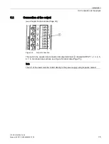
Страница 35: ... the output see Chapter Technical data Page 37 Figure 5 2 Output connection The loads to be supplied are connected at output terminals labeled OUTPUT 1 2 3 4 5 6 7 8 terminal cross sections see Figure Terminal data Page 11 Note The 0 V of the loads must be routed directly to the power supply using separate cables ...

Страница 36: ...Installation 5 2 Connection at the output SITOP SEL1200 1400 36 Manual 06 2019 A5E46496083 1 76 ...

Страница 37: ... apply for a rated input voltage rated load and 25 C ambient temperature if nothing else is specified 6 1 Input 6EP4438 7FB00 3DX0 6EP4438 7EB00 3DX0 Input Regulated DC voltage Rated voltage Uin rated 24 V Voltage range 20 4 30 V Overvoltage strength 35 V Input current at Uin rated Max 60 A ...

Страница 38: ...an 60 A 60 70 C derating 2 Iout K Adjustable response threshold 2 10 A Connecting outputs in parallel Yes max 4 2 outputs each that must lie next to one another Switching on outputs All outputs are switched on after the supply voltage ramps up 20 V delay time of 25 ms 200 ms 500 ms or load opti mized selectable using DIP switch Shutdown characteristics Figure 6 1 Shutdown characteristic The follow...

Страница 39: ... 10 ms to 100 ms the output is electronically shut down LED of the output is lit red An output current is continuously permissible up to the selected current response threshold LED of the output is lit green In the range 100 150 of the selected current response threshold an overload current is permissible for 5 seconds LED of the output flashes green then the output is electronically shut down LED...

Страница 40: ...en for Output switched on LED orange flashing for Output manually switched off LED red for Output switched off due to overload or overvoltage all LEDs flashing red for Device overload total max output current exceeded red running light for Device overtemperature More detailed information is provided in Chapter Status displays and signaling Page 13 Signaling Group signaling contact NO contact conta...

Страница 41: ...ed Group signaling contact 13 14 2 spring loaded terminals for 0 2 1 5 mm 0 2 1 5 mm solid finely stranded Not assigned NF one spring loaded terminal for 0 2 1 5 mm 0 2 1 5 mm solid finely stranded Remote reset RST one spring loaded terminal for 0 2 1 5 mm 0 2 1 5 mm solid finely stranded Width of the housing 45 mm Height of the housing 135 mm Depth of the housing 125 mm Installation width 45 mm M...

Страница 42: ...hat can be downloaded from the Internet 6EP4438 7FB00 3DX0 https www automation siemens com bilddb index aspx objkey G_KT01_XX_01575 gridvi ew view1 currentpage 1 pagesize 12 showdetail False view Search 6EP4438 7EB00 3DX0 https www automation siemens com bilddb index aspx objkey G_KT01_XX_01578 gridvi ew view1 currentpage 1 pagesize 12 showdetail False view Search ...

Страница 43: ...anual 06 2019 A5E46496083 1 76 43 Safety approvals EMC 7 7 1 Safety 6EP4438 7FB00 3DX0 6EP4438 7EB00 3DX0 Standard for safety acc to EN 60079 0 and EN 60079 15 Protection class Class III Degree of protection EN 60529 IP20 ...

Страница 44: ... 35 EU 2014 30 EU 2011 65 EU being prepared 2014 34 EU CB approval Yes UL cUL CSA approval UR UL 2367 file E328600 cULus UL 508 CSA C22 2 No 107 1 file E197259 cCSAus approval Available soon Explosion protection Available soon ATEX approval Available soon IECEx approval Available soon cULus HazLoc Available soon Marine approvals Available soon RCM Yes EAC Yes ...

Страница 45: ... 6000 MHz 10 V m 900 MHz 5 MHz 10 V m Fast transient disturbance va riables burst EN 61000 4 4 2 kV at the DC input 2 kV at the DC output Surge voltages EN 61000 4 5 0 5 kV symmetrical at the DC input 0 5 kV symmetrical at the DC output High frequency fields EN 61000 4 6 10 V 0 15 80 MHz Magnetic fields EN 61000 4 8 30 A m 50 Hz Generic standards EN 61000 6 2 Noise immunity for industrial environm...

Страница 46: ...Safety approvals EMC 7 3 EMC SITOP SEL1200 1400 46 Manual 06 2019 A5E46496083 1 76 ...

Страница 47: ... according to EN 60721 5 95 no condensation Degree of pollution 2 Mechanical stressing in operation Test according to EN 60068 2 6 vibration test Fc 3 5 mm deflection in the range 5 8 4 Hz 2 g acceleration in the range 8 4 150 Hz Test according to EN 60068 2 27 shock test Ea acceleration 150 m s2 test duration 11 ms Damaging gases Sulfur dioxide 10 cm3 m3 4 days Hydrogen sulfide 1 cm3 m3 4 days Te...

Страница 48: ...Ambient conditions SITOP SEL1200 1400 48 Manual 06 2019 A5E46496083 1 76 ...

Страница 49: ...nvironment 9 The devices are in conformance with RoHS As a rule only non silicon precipitating materials are used Disposal guidelines Packaging and packaging aids can and should always be recycled The product itself may not be disposed of as domestic refuse ...

Страница 50: ...Environment SITOP SEL1200 1400 50 Manual 06 2019 A5E46496083 1 76 ...

Страница 51: ...material SITOP information can be downloaded from the Internet Information and download center http www siemens com sitop infomaterial CAx data 2D 3D data and circuit diagram macros can be downloaded from the Internet Siemens image database http www siemens com sitop cax Request all CAx data via the CAx download manager CAx shopping cart http www siemens com cax SITOP Selection Tool Simply and qui...

Страница 52: ... Support SITOP SEL1200 1400 52 Manual 06 2019 A5E46496083 1 76 You can find these addresses as follows On the Internet http www automation siemens com partner Industry Mall http www siemens com industrymall de ...

Отзывы: