background image

4 Redundant 24 V DC power supply 
 

Integration of a SITOP 24V power supply in PCS 7 
Entry ID: 10948108,    V3.2,    01/2019 


22 


 S

iem

e

n

s A

2

0

1

9

 A

ll r

igh

ts 

re

se

rv

e

d


4.2 

Copying process tag types 

Before starting to create the AS program, it is advisable to copy the necessary plan 
templates to the master data library of the PCS 7 project. Process tag type 
"PSU2ModulesRed" is available for the redundant power supply. This process tag 
type contains the three "Pcs7DiIn" driver blocks and three "MonDiL" monitoring 
blocks that have already been interconnected correctly. 

Proceed as follows: 

1.  Open the SITOP library "SITOP_APL_V3_2". 

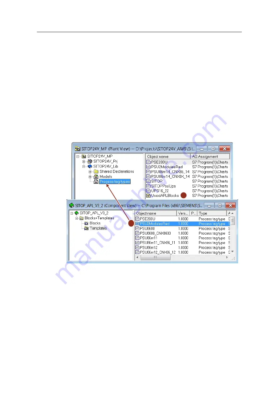
2.  Copy process tag type "PSU2ModulesRed" (1) to the "Process tag types" 

folder in the master data library. 

3.  Make sure that you copy the APL blocks that are used to the master data 

library too. To do this, create a CFC plan (2) by copying blocks "Pcs7DiIn" and 
"MonDiL" from the PCS 7 AP Library. 


Figure 4-3: 

1

2


Содержание SITOP PSE200U

Страница 1: ...Integration of a SITOP 24 V power supply in PCS 7 PSU8600 PSU8200 PSE202U PSE200U UPS1600 SIMATIC PCS 7 V9 0 SP1 https support industry siemens com cs ww en view 10948108 Siemens Industry Online Support ...

Страница 2: ... Claims for damages arising from a breach of material contractual obligations shall however be limited to the foreseeable damage typical of the type of agreement unless liability arises from intent or gross negligence or is based on loss of life bodily injury or damage to health The foregoing provisions do not imply any change in the burden of proof to your detriment You shall indemnify Siemens ag...

Страница 3: ... 28 5 1 UPS1600 on PROFINET IO field bus 28 5 1 1 Setting up the hardware configuration 28 5 1 2 Copying process tag types 34 5 1 3 Creating an AS program 35 5 1 4 Messages 36 5 2 UPS1600 with monitoring of the signal contacts 37 5 2 1 Setting up the hardware configuration 38 5 2 2 Copying process tag types 38 5 2 3 Creating an AS program 40 5 2 4 Parameterizing messages 43 5 3 Creating a process ...

Страница 4: ...ning the demo project 82 9 1 Installation 82 9 2 Operating SITOP modular 84 9 2 1 Overview of the power supply 84 9 2 2 Monitoring of redundancy 85 9 2 3 Monitoring of the DC USV 86 9 2 4 Monitoring the selectivity module 90 9 3 Operating the PSU8600 power supply system 91 9 3 1 Overview of the power supply system 91 9 3 2 Monitoring the power supply system 95 9 3 3 Monitoring of the PSU8600 with ...

Страница 5: ...y can be extended on a scalable basis In the present application example we will go into the details of the following configurations Redundant 24 V DC power supply Buffered 24 V power supply with battery storage Selective monitoring of individual 24 V feeders Power supply system SITOP PSU8600 SITOP PSU8600 power supply system with redundant basic modules Figure 1 1 SITOP UPS1100 SITOP UPS1600 SITO...

Страница 6: ...supply of the PCS 7 automation technology is implemented using SITOP modular power supply units and the associated expansion modules or using the SITOP PSU8600 power supply system The application example shows how to configure the hardware in the SIMATIC Manager and to easily integrate it into the PCS 7 control system Default blocks from the PCS 7 Advanced Process Library and product specific bloc...

Страница 7: ...t uses SITOP PSU8200 power supply units the SITOP PSE202U redundancy module the SITOP UPS1600 UPS1100 uninterruptible power supply with battery module and the SITOP PSE200U selectivity module Figure 1 2 OS Server OS Client Industrial Ethernet PROFINET IO 120 230V AC DC 24V DC 24V GND UPS1600 UPS1100 2x PSU8200 PSE202U Switch AS ET 200 SCALANCE PSE200U ET 200 ...

Страница 8: ... four selectively monitored outputs CNX8600 Using the BUF8600 buffer module it is possible to bypass brownouts If the short term bridging with the buffer module is not sufficient a longer period can be bridged with the UPS module UPS8600 and the batteries connected to it BAT8600 Figure 1 3 Industrial Ethernet PROFINET IO DC 24V DC 24V GND Switch AC 400V AC 120V 230V 4x DC 24V Selective 4x DC 24V S...

Страница 9: ...le 4x 3 A PSU8600 2 6EP3436 8SB00 2AY0 Power supply system DC 24 V 1x 20 A PSU8600 1 6EP3437 8MB00 2CY0 Power supply system DC 24 V 4x 10 A CNX8600 1 6EP4437 8XB00 0CY0 Expansion module 4x 10 A BUF8600 1 6EP4297 8HB10 0XY0 Buffer module 300 ms 40 A UPS8600 1 6EP4197 8AB00 0XY0 USV module V1 4 BAT8600 1 6EP4145 8GB00 0XY0 Battery Pb 380Wh Software components Table 1 2 Component Qty Article number N...

Страница 10: ... high degree of safety even when large voltage fluctuations occur They offer outstanding overload characteristics Power boost delivers up to three times the rated current for short periods of time and with extra power of 150 loads with high power consumption can be connected without any problems The very high degree of effectivity keeps energy consumption and heat dissipation in the control cabine...

Страница 11: ...ically supplies the power Additionally a signal is sent via a signal contact that can be evaluated by a controller PC or control system You can find detailed information here SITOP Redundancy module Figure 2 2 120 230V AC DC 24V Redundant PSU8200 PSE202U Signal SU 2 1 24V K Signal PSU8200 2 24V K Signal PSE202U 24V K Alternatively the PROFINET capable PSU8600 power supply system with one output an...

Страница 12: ...Figure 3 3 The UPS1600 s intelligent battery management and communication via the Energy Storage Link ensure optimal charging and continuous monitoring of the UPS1100 battery modules The buffer time of the DC UPS depends on the load current and capacity and the number of battery modules When choosing the correct DC USV configuration the SITOP Selection Tool helps you in an optimum way You can find...

Страница 13: ...uptible power supply DC 24V 10A with PN IE connection integrated web server integrated OPC UA server from firmware V2 2 firmware V1 2 V2 0 V2 1 V2 2 UPS1600 20A PN Uninterruptible power supply DC 24V 20A with PN IE connection web server integrated firmware V2 0 UPS1600 20A PN LS V Uninterruptible power supply DC 24V 20A with PN IE connection integrated web server integrated OPC UA server from firm...

Страница 14: ...cuits The intact branches continue to supply the SITOP selectivity modules with 24 V without any interruption or feedback The sum signal contact can be evaluated for each selectivity module but can also be looped through several modules For selectivity modules with single channel reporting the serial code is decoded by a function block via the status of each output Both sum and single channel mess...

Страница 15: ...c unit provides either one selectively monitored output or four selectively monitored outputs Figure 3 5 Using the power boost of 150 loads with high power consumption can be connected without any problems The modular system with the innovative System Clip Link connection system allows for an individual combination of the power supply system without needing additional wiring The order of the expan...

Страница 16: ...C 24V 20A 4x 5A with PN IE connection web server integrated OPC UA server integrated firmware V1 1 1 4 PSU8600 3ph 40A PN V1 1 1 4 Regulated power supply DC 24V 20A with PN IE connection integrated web server integrated OPC UA server Firmware V1 1 1 4 PSU8600 3ph 20A PN V1 1 1 4 Regulated power supply DC 24V 20A with PN IE connection integrated web server integrated OPC UA server Firmware V1 1 1 4...

Страница 17: ...rights reserved The device master data of the PSU8600 are integrated into the folder PROFINET IO I O PSU8600 The subordinate folders of the basic devices contain the master data of the extension modules CNX8600 BUF8600 and UPS8600 For the UPS8600 module the master data of the BAT8600 is also available Figure 2 8 ...

Страница 18: ...rst update the APL devices Proceed as follows 1 Open the library SITOP_APL_V3_2 with the SIMATIC manager This is copied by the installation into the directory Program Files x86 SIEMENS STEP7 S7libs 2 Copy the following APL blocks to the Blocks directory of the library MonDiL FB1848 Pcs7DiIn FB1871 Figure 3 1 3 Switch to the Templates folder and open the process tag type SITOP This plan contains th...

Страница 19: ...eserved 6 Confirm the Convert Format dialog with Yes In this way all CFC charts are converted to the new format Figure 3 3 7 In the Import New Versions dialog confirm that the blocks in the CFC charts are replaced with the new version Figure 3 4 Note The update takes place for all process tag types in the library that use these blocks ...

Страница 20: ...its To monitor redundancy the signal contact of the redundancy module is connected to one of the digital inputs of the external peripherals The signal contact is designed as a changeover switch and can thus signal the good or the bad state Apart from this it is possible to connect the power supply units to the external peripherals The signal contact of the power supply units is designed as normall...

Страница 21: ...ts and the redundancy module the signal contacts are each connected to one of the digital inputs of the external peripherals and symbolized appropriately in the hardware configuration Proceed as follows 1 In SIMATIC Manager open the hardware configuration of the automation system 2 Highlight the digital input assembly of the external peripherals 1 and choose menu command Edit Symbols 3 Enter an ap...

Страница 22: ...esRed is available for the redundant power supply This process tag type contains the three Pcs7DiIn driver blocks and three MonDiL monitoring blocks that have already been interconnected correctly Proceed as follows 1 Open the SITOP library SITOP_APL_V3_2 2 Copy process tag type PSU2ModulesRed 1 to the Process tag types folder in the master data library 3 Make sure that you copy the APL blocks tha...

Страница 23: ...Figure 4 4 1 2 Open the CFC plan and carry out the following adjustments for each input signal Rename the monitoring blocks to match their uses 2 Interconnect inputs PV_In with the corresponding symbols of the external peripherals 3 Invert the In input signals 4 on the monitoring blocks of the power supply units since their signal contact is closed in the good state At the Color inputs of the moni...

Страница 24: ...ration of a SITOP 24V power supply in PCS 7 Entry ID 10948108 V3 2 01 2019 24 Siemens AG 2019 All rights reserved Figure 4 5 2 3 4 5 3 Compile the AS program and update the view of the CFC plan 4 Load the program into the automation system ...

Страница 25: ...after the other and click on the Messages pushbutton 2 In the message configuration dialog change the message text 1 However leave the BlockComment system instruction in the message text 3 Click on the Save pushbutton 2 to confirm your change 4 Close the properties of the monitoring block Figure 4 6 2 1 Note If you need message texts in several languages you use the menu command ools Manage multil...

Страница 26: ...g one 1 in the folder of the technological hierarchy in which the CFC plan that you edited before is located Figure 4 7 1 2 Execute the Compile OS function so that the system creates the process variables and the messages in the OS project as well as the block icons in the process picture 3 Open the process picture using the WinCC Graphics Designer 4 Draw the process picture as you want it to appe...

Страница 27: ...ion to the block icons With the squares the background color is dynamized and linked to the process values of the monitoring blocks OUT Value 0 green OUT Value 1 red 4 6 Runtime After starting the OS runtime and switching to the corresponding technological hierarchy it is now possible to monitor the status of the redundant power supply on the OS The system issues a message if the threshold voltage...

Страница 28: ...ring via Industrial Ethernet on the plant bus Monitoring the signal contacts via the external peripherals Below we will describe configuration of both options in the SIMATIC Manager There is no difference between OS configuration of both variants 5 1 UPS1600 on PROFINET IO field bus You can parameterize the DC UPS module in the SIMATIC Manager using the Generic Station Description Monitoring of th...

Страница 29: ...PROFINET IO on the automation system s fieldbus f you have not already done so you must first adapt the IP address and the device name of the UPS to the network configuration of the fieldbus Note To parameterize the Ethernet nodes they must be on the same physical network as the ES After this you can make the separation between the plant bus and the process bus field level Proceed as follows 1 Mak...

Страница 30: ...click on the Browse pushbutton 1 in the Ethernet Node area 4 In the Browse Network dialog choose the UPS1600 from the list of nodes and click on OK to confirm your selection 5 Edit the IP address to match your network configuration and click on the Assign IP Configuration pushbutton 2 6 Edit the device name and click on the Assign Name pushbutton 3 7 Close the dialog again Figure 5 2 1 2 3 ...

Страница 31: ...19 All rights reserved Configuring the hardware The next thing to do is to update the UPS1600 in the hardware configuration Proceed as follows 1 Drag the UPS1600 from the device catalog 1 onto the PROFINET IO system of the AS 2 Open the properties of the DC UPS and enter the device name 2 and the device s address 3 Figure 5 3 1 2 3 ...

Страница 32: ...UPS1600 in the HW configuration too You can find more detailed information on the different parameters in the manual entitled SITOP UPS1600 UPS1100 Proceed as follows 1 Select the DC UPS 1 in the hardware configuration 2 Open the properties of the UPS1600 xxA PN module 2 on slot 0 1 by double clicking 3 Switch to the Parameters tab 4 Set the parameters 3 as required here 5 Compile and load the har...

Страница 33: ... the REN position 1 Configuring symbols To interconnect the driver block of the control program with a symbolic address at a later time parameterize the I O addresses of the DC UPS using symbols Proceed as follows 1 Select the DC UPS 1 in the hardware configuration 2 Highlight module UPS1600 xxA PN 2 on slot 0 2 and execute menu command Edit Symbols 3 Click on the Add to Symbols pushbutton This au...

Страница 34: ...s tag type UPS1600 UPS16_21 and UPS16_22 These plans each contain a driver block DrvUPS and a monitoring block UPS1600 for the respective firmware version of the UPS device The blocks have already been correctly interconnected with one another Proceed as follows 1 Open SITOP library SITOP_APL_V3 2 Copy one of the UPS16xxx templates 1 depending on the firmware of the device used into the Process ta...

Страница 35: ...p it in the desired folder in the technological hierarchy and rename it 1 Figure 5 7 1 2 Open the plan and carry out the following modifications 3 Interconnect input PV_In to the first input address of the UPS1600 If you have used the standard symbols the symbol is called IBxxx_Input voltage 2 4 Rename the monitoring block to match its use 3 Figure 5 8 2 3 5 Compile the AS program and update the v...

Страница 36: ...a SITOP 24V power supply in PCS 7 Entry ID 10948108 V3 2 01 2019 36 Siemens AG 2019 All rights reserved 5 1 4 Messages The messages of the SITOP UPS1600 have already been parameterized in the function block and you do not need to change them Figure 5 9 ...

Страница 37: ...t Industrial Ethernet PROFINET IO 120 230V AC AS ET 200 SCALANCE DC 24V DC 24V GND UPS1600 UPS1100 PSU8200 PSE202U Switch Signal The UPS1600 makes available the following three signal contacts for signaling the status Relay 1 Buffering mode or OFF changeover switch Relay 2 Buffer not ready rechargeable battery defective changeover switch The system displays a defective rechargeable battery by the ...

Страница 38: ...using appropriate symbols Proceed as follows 1 In SIMATIC Manager open the hardware configuration of the automation system 2 Highlight the digital input assembly of the external peripherals 1 and choose menu command Edit Symbols 3 At the inputs that are connected to the DC UPS enter an appropriate symbolic name 2 4 Click on OK to confirm your changes 5 Compile and load the changed hardware configu...

Страница 39: ...s reserved Proceed as follows 1 Open the SITOP library SITOP_APL_V3_2 2 Copy the SITOP template 1 to the Process tag types folder in the master data library 3 Make sure that you copy the APL blocks that are used to the master data library too To do this create a CFC plan 2 by copying blocks Pcs7DiIn and MonDiL from the PCS 7 APL Figure 5 13 2 1 ...

Страница 40: ... to monitor buffering mode Rel 1 Rename the monitoring block 2 to match its use Here the system monitors the signal for buffering mode Interconnect input PV_In with the corresponding symbol of the external peripherals 3 At the Color input 4 of the monitoring block parameterize the value 16 2 This is so that the system displays the value in yellow in the faceplate in accordance with a warning Figur...

Страница 41: ...s This makes it possible for the block to detect signal flutter 1 In the example this property is used to collect the 0 25 Hz signal for a defective battery At the Color input 8 of the monitoring block parameterize the value 16 1 This is so that the system displays the value in red in the faceplate in accordance with an alarm Figure 5 16 5 6 7 8 1 If the input signal state changes in the specified...

Страница 42: ... again Carry out the modifications below for monitoring the battery charge Rel 3 Rename the monitoring block 9 to match its use Here the system monitors the Battery charge 85 signal Interconnect input PV_In with the corresponding symbol of the external peripherals 10 At parameters FlutTmIn 0 0 and Color 16 0 you use the default values Figure 5 17 9 10 5 Compile the AS program and update the view o...

Страница 43: ...message text and the message class to Warning high 2 At SIG1 und SIG2 of battery monitoring 2 change the message text and the message class to Alarm high 3 At SIG1 of status monitoring 3 change the message text and the message class to Process Message With Acknowledgement Figure 5 18 1 2 3 Note If you need message texts in several languages you use the menu command ools Manage multilingual texts C...

Страница 44: ...the variant that you used to monitor the DC UPS the Compile OS function generates the corresponding block icons in the process picture In this example both variants were configured Proceed as follows 1 Create a new process picture or open an existing one 1 in the folder of the technological hierarchy in which the CFC plan that you edited before is located Figure 5 19 1 2 Execute the Compile OS fun...

Страница 45: ...cture 5 Save the adapted process picture and close it Figure 5 20 2 3 5 4 Runtime After starting runtime and switching to the corresponding technological hierarchy it is possible to monitor the status of the uninterruptible power supply on the OS The block icon 1 shows the current charge of the battery and indicates pending messages In the faceplate 2 you get detailed information about the operati...

Страница 46: ... supply in PCS 7 Entry ID 10948108 V3 2 01 2019 46 Siemens AG 2019 All rights reserved Figure 5 21 1 2 3 The UPS1600 also signals the status via the signaling contacts which are connected to the external peripherals and are visualized on the OS via the status displays 3 ...

Страница 47: ...lly in the case of a fault Different versions of the selectivity module are available each of which has an output current range of 5 3 or 3 1 In the example we used a module with a common alarm The signal contact is executed as a changeover switch which means that it can signal the good and bad states A remote reset from a central location is also possible Figure 6 1 OS Server OS Client AS PSU8200...

Страница 48: ... of the digital outputs of the external peripherals and symbolized appropriately in the hardware configuration Proceed as follows 1 In SIMATIC Manager open the hardware configuration of the automation system 2 Highlight the digital input assembly of the external peripherals 1 and choose menu command Edit Symbols 3 At the input that is connected to the selectivity module enter an appropriate symbol...

Страница 49: ...g OB38 10ms This is necessary so that the diagnostics block can record the time sequence of the signal change Figure 6 3 CFC plan for monitoring a selectivity module with single channel reporting In the present example we used a selectivity module with a common signaling contact You can use the SITOP process tag type for this module This tag type contains the APL blocks for collecting a digital in...

Страница 50: ...e monitoring of 24V feeders Integration of a SITOP 24V power supply in PCS 7 Entry ID 10948108 V3 2 01 2019 50 Siemens AG 2019 All rights reserved Figure 6 4 Copy measuring point types to the project library 2 1 ...

Страница 51: ...nal peripherals 3 At the Color input 4 of the monitoring block parameterize the value 16 1 This is so that the system displays the value in red in the faceplate in accordance with an alarm Figure 6 6 CFC plan for recording the sum error in the selectivity module 2 3 4 3 For a remote reset at the Operator Station you must add to the program a digital output driver block and an operation block for d...

Страница 52: ...view of the CFC plan 5 Load the program into the automation system 6 4 Parameterizing a message So that the operator is informed of a failure of a 24 V branch the message of the monitoring module is also adapted Proceed as follows 1 Open the properties view of the MonDiL block and click on the Messages pushbutton 2 In the message configuration dialog change the message text 1 However leave the Blo...

Страница 53: ...eed as follows 1 If not already done create a new process picture 1 in the folder of the technological hierarchy in which the previously edited CFC chart is located Figure 6 9 1 2 Execute the Compile OS function so that the process variables the messages and the block icon in the OS project are generated 3 Open the process picture using the WinCC Graphics Designer 4 Draw the process picture as des...

Страница 54: ...3 2 01 2019 54 Siemens AG 2019 All rights reserved Figure 6 10 2 3 4 Note In the example additional color areas have been configured that symbolically represent the state of the module as LED lamps In the color areas the background color is dynamized and linked to the process value of the monitoring blocks ...

Страница 55: ...ts reserved 6 6 Runtime After starting runtime and switching to the corresponding technological hierarchy it is now possible to monitor the status of the selectivity module on the OS Apart from this the system issues a message in the case of a fault Once you have eliminated the fault you can reset the module using the operator block Figure 6 11 ...

Страница 56: ...with selective monitoring is connected to the basic module You can set the current response thresholds individually for each output A buffer module BUF8600 is plugged in for so called brownouts In addition the UPS8600 UPS module in conjunction with the BAT8600 is available for power failures over a longer period of time Figure 7 1 Industrial Ethernet PROFINET IO DC 24V DC 24V GND Switch AC 400V AC...

Страница 57: ...e so you must first adapt the IP address and the device name of the PSU to the network configuration of the fieldbus Note To parameterize the Ethernet nodes they must be on the same physical network as the ES After this you can make the separation between the plant bus and the process bus field level Proceed as follows 1 Make sure that the device is on the same physical network as the configuratio...

Страница 58: ...7 Power supply system SITOP PSU8600 Integration of a SITOP 24V power supply in PCS 7 Entry ID 10948108 V3 2 01 2019 58 Siemens AG 2019 All rights reserved Figure 7 2 1 2 3 ...

Страница 59: ... system of the AS 2 Mark the PROFINET IO device and drag an extension module CNX8600 a buffer module BUF8600 and a UPS module UPS8600 2 to a free slot of the basic module A maximum of five slots per basic module are available 3 Pull a battery into one of the slots of the UPS8600 module 3 A maximum of five slots are available for batteries of the same type 4 Open the properties of the PSU and enter...

Страница 60: ... in the SITOP PSU8600 manual at the following link https support industry siemens com cs ww en view 105867947 Proceed as follows 1 Select the PSU8600 1 in the hardware configuration 2 Open the properties of the PSU8600 3ph module 2 on slot 0 1 by double clicking 3 Switch to the Parameters tab and set the parameters 3 as desired 4 Open the properties of the 24 V outputs one after the other 4 and se...

Страница 61: ...HW configuration is only effective if you have set the REN DIP switch 1 on the device to the ON position 1 Configuring symbols To interconnect the driver block of the control program with a symbolic address at a later time parameterize the I O addresses of the basic module using symbols Proceed as follows 1 Select the PSU8600 in the hardware configuration 2 Highlight module PSU8600 3ph on slot 0 2...

Страница 62: ... Compile and load the hardware configuration Figure 7 5 1 Configuring the web server It is also possible to use the web server of the PSU8600 This enables remote access to the PSU8600 via a web browser Proceed as follows to activate the web server 1 Check that the DIP switch REN Remote enable is set to ON 2 Open in the HW Config the properties of the module PSU8600 3ph at slot 0 1 with a double cl...

Страница 63: ...e hardware configuration The web server is now activated and can be used 6 Open a web browser e g Internet Explorer 7 Enter the IP address of the PSU8600 in the address field The login screen of the PSU8600 opens Figure 7 7 8 Log in with your preconfigured login data Name admin Password admin After logging in you can view the operating data alarms and hardware configuration In addition you can per...

Страница 64: ...ower supply system at the following link https support industry siemens com cs ww en view 102295547 The function blocks of the used SITOP PSU8600 FW V1 4 with 4 outputs and a CNX8600 expansion module are configured in the measuring point type PSU86m14_CNX86_14 This contains a driver block Dr86_14 the monitoring block PSU86m12 and four blocks CNX86_14 of the expansion modules The blocks have alread...

Страница 65: ...er of the technological hierarchy and rename it 1 Figure 7 10 1 2 Open the CFC plan and carry out the following modifications in the AS program Open Properties of PSU86m14 and rename it according to its use 2 Parameterize a symbol variant 3 Eleven symbols are available Depending on the variant you have chosen the measured currents of the basic module or those of the expansion module are shown in t...

Страница 66: ... All rights reserved Interconnect input AddrIn 4 with the corresponding symbol of the PSU8600 from the hardware configuration Delete the CNX2 CNX3 and CNX4 blocks of the expansion modules if you do not need them Figure 7 12 2 4 3 3 Compile the AS program and update the view of the CFC plan 4 Load the program into the automation system ...

Страница 67: ...for PCS 7 also copied the block icons and faceplates for the display of the PSU8600 on the OS The Compile OS function generates the corresponding block icons in the process picture Proceed as follows 1 Create a new process picture or open an existing one 1 in the folder of the technological hierarchy in which the CFC plan that you edited before is located Figure 7 14 1 2 Execute the Compile OS fun...

Страница 68: ...in PCS 7 Entry ID 10948108 V3 2 01 2019 68 Siemens AG 2019 All rights reserved 4 Draw the process picture as you want it to appear and position the block icon of the PSU8600 2 at the intended location in the picture 5 Save the adapted process picture and close it Figure 7 15 2 ...

Страница 69: ... supply in PCS 7 Entry ID 10948108 V3 2 01 2019 69 Siemens AG 2019 All rights reserved 7 6 Runtime After starting runtime and switching to the corresponding technological hierarchy it is now possible to monitor the status of the power supply system on the OS Figure 7 16 ...

Страница 70: ...n with two PSU8600 power supplies requires the use of an identical basic type with a 24 V output The adjustable current response thresholds must be parameterized identically In order to disconnect the two 24V basic devices from one another the redundancy module PSE202U is used Figure 8 1 OS Server OS Client Industrial Ethernet PROFINET IO AC 230V 120V AS PSU8600 PSE202U ET 200 SCALANCE DC 24V DC 2...

Страница 71: ...n the item entitled GSD for SITOP PSU8600 for integration in STEP 7 V5 at the following link https support industry siemens com cs ww en view 102254061 Parameterizing Ethernet nodes The SITOP PSU8600 communicates by means of PROFINET IO on the automation system s fieldbus f you have not already done so you must first adapt the IP address and the device name of both power supply units to the networ...

Страница 72: ...mmand Target system Edit Ethernet Node 3 In the Edit Ethernet Node dialog click on the Browse pushbutton 1 in the Ethernet Node area 4 In the Browse Network dialog choose the PSU8600 from the list of nodes and click on OK to confirm your selection 5 Edit the IP address to match your network configuration and click on the Assign IP Configuration pushbutton 2 6 Edit the device name and click on the ...

Страница 73: ...ights reserved Configuring the hardware Proceed as follows 1 Drag the two identical PSU8600 from the device catalog 1 onto the PROFINET IO system of the AS Note that only devices with a 24V output can be used 2 Open the properties of both PSUs in succession and enter the device name 2 and parameterize the IP address 3 of the devices Figure 8 3 1 3 2 ...

Страница 74: ...ion Figure 8 4 1 1 Setting the SITOP PSU8600 parameters commissioning In the HW configuration for the PSU8600 you can set general parameters parameters for R F energy and the output parameters of the basic module s and the expansion module s 24 V outputs You can find more detailed information on the different parameters in the SITOP PSU8600 manual at the following link https support industry sieme...

Страница 75: ...er supply in PCS 7 Entry ID 10948108 V3 2 01 2019 75 Siemens AG 2019 All rights reserved Figure 8 5 2 4 1 3 Note Bear in mind that remote parameterization by means of the HW configuration is only effective if you have set the REN DIP switch 1 on the device to the ON position 1 ...

Страница 76: ...ring point type PSU86s14_CNX86_14 This contains a driver block Dr86s_14 and the monitoring block PSU86s14 The blocks have already been correctly interconnected with one another The Redundancy module PSE202U features a signaling contact connected with the de centralized peripherals The required modules for the monitoring a digital input signal are part of the process tag type SITOP Proceed as follo...

Страница 77: ...2 Create one instance of the measuring point type PSU86s14_CNX86_14 2 for each PSU8600 Rename both plans correspondingly Figure 8 7 1 2 3 Open the CFC plan of the redundancy module and carry out the following adjustments Rename the monitoring block MonDiL in line with its use 3 This name is later displayed in the OS in addition to the plan name Interconnect input PV_In of Pcs7DiIn module with the ...

Страница 78: ...played in the OS in addition to the plan name Figure 8 9 6 7 5 Compile the AS program and update the view of the CFC plan 6 Load the program into the automation system 8 4 Messages The MonDiL APL block is used to monitor the redundancy module The standard display text is parameterized for it In order to assign the message to the event better you can adjust the display text as follows 1 Open the pr...

Страница 79: ...veral languages you use the menu command ools Manage multilingual texts Change language in the S M C Manager to change the language for display texts and adapt the text in the message configuration for the set language The messages of the SITOP PSU8600 power supply have already been parameterized in the function block and you do not need to change them However if required you can adapt the message...

Страница 80: ...e Proceed as follows 1 Create a new process picture or open an existing one 1 in the folder of the technological hierarchy in which the CFC plan that you edited before is located Figure 8 12 1 2 Execute the Compile OS function so that the process variables the messages and the block icon in the OS project are generated 3 Open the process picture using the WinCC Graphics Designer 4 Draw the process...

Страница 81: ...n PCS 7 Entry ID 10948108 V3 2 01 2019 81 Siemens AG 2019 All rights reserved 8 6 Runtime After starting runtime and switching to the corresponding technological hierarchy it is now possible to monitor the status of both power supply systems and the redundancy module on the OS Figure 8 14 ...

Страница 82: ...n your engineering system The GSD and a corresponding installation manual for the SITOP UPS1600 can be found in the entry GSD for SITOP UPS1600 for integration in STEP 7 V5 in the following link https support industry siemens com cs ww en view 75854605 The GSD and a corresponding installation manual for the SITOP PSU8600 can be found in the entry GSD for SITOP PSU8600 for integration in STEP 7 V5 ...

Страница 83: ... connections in NETPro Compiling and loading the AS program Compile and load the OS project If there is no CPU 410 5H available configure a new automation system Proceed as follows 1 Create an AS according to your existing hardware 2 Configure the external peripherals as shown in sections 4 1 5 1 1 5 2 1 6 1 7 1 and 8 1 3 Switch to the view of the technological hierarchy and change the AS assignme...

Страница 84: ...icture the system gives you the information below or you can carry out these operations Operating status of the power supply units 1 Failure of redundancy or falling short of the voltage threshold 2 Status of the UPS when connected to Industrial Ethernet 3 Status of the UPS when monitoring the signal contacts 4 Short circuit or overloading of a 24 V feeder 5 Reset of the selectivity module 6 Displ...

Страница 85: ...ncy You can call up the picture by switching to the SITOP Redundancy sub area Figure 9 4 In the process picture you get the following information Operating status of the power supply units 1 Failure of redundancy or falling below the parameterized voltage threshold 2 Figure 9 5 1 2 The block icons of the digital inputs for the redundancy module and the power supply units come from the PCS 7 Advanc...

Страница 86: ...uptible power supply You can call up the picture by switching to the SITOP Buffering sub area Figure 9 6 In the process picture you get the following information Status of the UPS when connected to Industrial Ethernet 1 Status of the UPS when monitoring the signal contacts 2 Figure 9 7 1 2 The block icons of the digital inputs for monitoring the signal contacts of the DC UPS come from the PCS 7 Ad...

Страница 87: ...ck icon with faceplate By installing the SITOP library the necessary components are copied to your system Below we will give you a brief description displays on the Operator Station Block icon You can see the following information in this symbol Battery charge status Active message Saved note Figure 9 8 Faceplate The faceplate for the UPS1600 makes available the following views Standard view Alarm...

Страница 88: ... V3 2 01 2019 88 Siemens AG 2019 All rights reserved Standard view In the standard view you get detailed information about the operating status of the DC UPS Figure 9 9 Alarm view Message view displays the messages of the block Here you can acknowledge single messages or all the messages Figure 9 10 ...

Страница 89: ... view In trend view you can display all the important values as a curve progression If value archiving is activated on the AS block you can switch between current values and archive values Figure 9 11 Note view In note view you can store messages for other operating or maintenance personnel The system displays an active message on the block icon Figure 9 12 ...

Страница 90: ... SITOP Selectivity sub area Figure 9 13 In the process picture you get the following information Operating status of the 24 V branches with a module with single channel alarm 1 Operating status of the 24 V branches for a module with common alarm 1 Resetting the module after eliminating the faults 3 Figure 9 14 3 1 2 The block icons of the digital inputs and the operation block for the selectivity ...

Страница 91: ...ss diagram the device symbols of the PSU8600 with selectivity buffer UPS module and battery 1 as well as the redundantly designed PSU8600 with a 24V output and the symbol for the monitoring of the redundancy module 3 are applied Figure 9 15 1 2 3 2 When monitoring via Industrial Ethernet PROFINET the power supply system has its own block icon with faceplate By installing the SITOP library the nece...

Страница 92: ...ng power of the batteries 6 In the event of a fault the system displays a maintenance request 7 and changes the color of the output fields to black Figure 9 16 4 5 7 6 Faceplate The faceplate for the PSU8600 makes available the following views Standard view Alarm view corresponds to the APL standard Trend view corresponds to the APL standard Note view corresponds to the APL standard Batch view cor...

Страница 93: ...splaying the expansion modules The number of buttons that are displayed depends on the hardware configuration You can monitor the status of the expansion modules here Figure 9 18 8 Buffer modules Clicking on the Further Views button again takes you to the buttons for displaying the buffer modules The number of buttons that are displayed depends on the hardware configuration You can monitor the sta...

Страница 94: ...ews button again takes you to the buttons for displaying the buffer modules The number of buttons that are displayed depends on the hardware configuration In this view you can see the current status of the UPS module and the connected batteries Depending on the project planning up to five batteries of the same type and their charge state as well as general states are displayed Figure 9 20 ...

Страница 95: ...her process picture is configured for monitoring the PSU8600 power supply system You can call up the picture by switching to the PSU8600 System sub area Figure 9 21 The following information is displayed in the process picture Block icon 1 with basic module output currents Image block 2 for detailed display of the status of the PSU8600 including the expansion module the buffer module and the UPS m...

Страница 96: ...roject a further process picture is configured for redundancy monitoring with two PSU8600 power supply systems You can call the picture by switching to the PSU8600 Redundancy sub area Figure 9 23 In the process picture you get the following information Block icons of the power supply 1 Faceplate 2 for detailed display of the PSU8600 status Failure of redundancy or falling below the voltage thresho...

Страница 97: ...t contracts Please send queries to Technical Support via Web form www siemens com industry supportrequest SITRAIN Training for Industry We support you with our globally available training courses for industry with practical experience innovative learning methods and a concept that s tailored to the customer s specific needs For more information on our offered trainings and courses as well as their...

Страница 98: ...view 84977415 7 SITOP PSU8200 1ph manual https support industry siemens com cs ww en view 92575279 8 SITOP PSE202U Redundancy module Operating instructions https support industry siemens com cs ww en view 42248598 9 SITOP PSE200U Selectivity module manual https support industry siemens com cs ww en view 61777451 10 SITOP PSU8600 power supply system manual basic devices with four outputs https supp...

Страница 99: ...dated to SITOP Library V2 0 Expansion of the project through a redundant design of the power supply with SITOP PSU8600 Expansion and adaptation of documentation V3 0 02 2018 Demo project updated to PCS7 Version V9 0 Demo project updated to SITOP Library V3 0 Expansion and adaptation of documentation V3 2 01 2019 Demo project updated to PCS7 Version V9 0 SP1 Demo project updated to SITOP Library V3...

Отзывы: