Mounting and dismantling
4
4.1
Mounting 3RW55 and 3RW55 Failsafe soft starters
Procedure
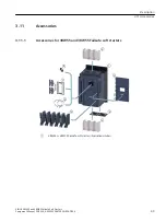
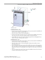
1. Optionally mount the fan cover (Page 55).
2. Mount the 3RW55 or 3RW55 Failsafe soft starter on a level surface (Page 56).
Ensure that the permissible temperature range and the necessary clearances are complied
with.
Technical data in Siemens Industry Online Support (Page 285)
3. You also have the option of mounting the 3RW5 communication module (accessory).
You will find further information in the manual for the 3RW5 communication module in
question.
Result
You have mounted the 3RW55 or 3RW55 Failsafe soft starter and can now connect it.
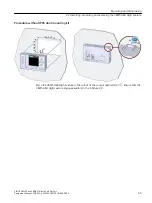
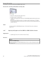
You can remove the 3RW5 HMI High Feature and install it in a control cabinet door, for example.
You can proceed as follows:
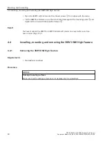
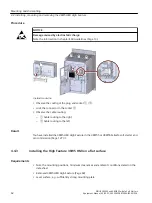
• Removing the 3RW5 HMI High Feature (Page 60)
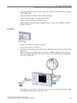
• Installing the 3RW5 HMI High Feature in the control cabinet door (Page 64)
• Installing the High Feature 3RW5 HMI on a flat surface (Page 62)
4.2
Mounting the fan cover
Requirements
• Screwdriver T20
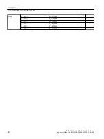
• Fan cover (accessory) suitable for the size
Size
Article number of the 3RW55 or
3RW55 Failsafe soft starter
Article number of the
fan cover
Number of required fan covers
Size 1
3RW551.-.....
3RW5983-0FC00
1
Size 2
3RW552.-.....
2
Size 3
3RW553.-.....
2
Size 4
3RW554.-.....
3RW5984-0FC00
1
Size 5
3RW555.-.....
3RW5985-0FC00
3
SIRIUS 3RW55 and 3RW55 Failsafe Soft Starters
Equipment Manual, 02/2022, A5E35630887002A/RS-AF/006
55


