


Installation of TFT displays
2 - 5
Siemens AG
SPR2-230.812.02
Page 5 of 8
SIREMOBIL
Medical Solutions
Rev. 02
02.06
CS PS SP
System Manual
Installation
2
•
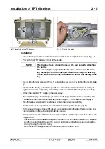
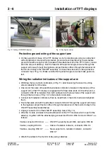
The collision protection is still removed on the left-hand and right-hand side (3/ Fig. 11).
•
Place the first TFT display in front of the holder.
•
Screw in both fixing screws (1/Fig. 11) only slightly, i.e. do not yet tighten them complete-
ly.
•
Shift the TFT display out until it is possible to screw in the external screws. Do not yet
tighten the screws completely. It must be possible to shift the TFT display horizontally.
•
Attach the second TFT display in the same way.
•
Place both displays horizontally symmetrical with respect to the center axis (2/Fig. 11).
- Make sure that there is a vertical clearance of approx. 2 mm between the displays.
•
If both displays are properly positioned, tighten the fixing screws firmly.
•
Reattach the collision protection on the left-hand and right-hand side (Fig. 9).
•
If it is required to adjust the width, insert a spacer ring on both sides, then push the colli-
sion protection in the tube and retighten its screws.
•
If required, correct the distance between the displays and the top and bottom tube of the
support arm.
- It is recommended to leave a couple of millimeters for ventilation between the displays
and the top and bottom tube of the support arm to prevent collisions due to vibrations
during moving the monitor trolley.
- Both tubes of the support arm should run in parallel to each other.
Fig. 11 Installation of the TFT displays
Fig. 12 Routing the cables
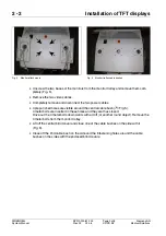
The displays have 4 thread holes on the rear panel for attaching
the holder.
For some displays, special adapter plates are needed for install-
ing the display on the holder (included in the scope of delivery).
These plates are to be inserted between holder and display hous-
ing.
NOTE