


SIREMOBIL
SPR2-230.812.02
Page 4 of 8
Siemens AG
System Manual
Rev. 02
02.06
CS PS SP
Medical Solutions
2 - 4
Installation of TFT displays
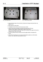
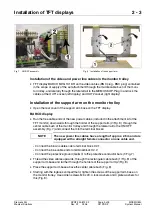
Installation of the TFT display on the support arm
•
Dismount temporarily the collision protection (see Fig. 9). To do so, loosen the screws (1/
Fig. 9) on both top tubes and pull out the collision protection.
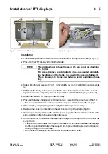
Adjusting the support arm to the size of the TFT display
2
•
After loosening the 2 x 8 countersunk screws on the support arm (
‰
/Fig. 10), you can
adjust the distance between both tubes as well as the vertical position of the holding
plate (A/Fig. 10).
•
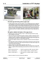
To permit easier adjustment, it is recommended to calculate and pre-set the
distances (1/Fig. 10) before the TFT displays are attached.
Calculation of the distances (1/Fig. 10):
•
Setting the distances results in a distance of approx. 1 cm between the top and bottom
edge of the TFT displays, on the one hand, and the tubes of the support arm, on the oth-
er hand.
Fig. 9 Collision protection
Fig. 10 Adjustment of the support arm
You can adjust the width of the support arm and the distance
between the top and bottom tube to adapt the support arm to the
display in use. In addition, you can modify the vertical centering
of the holding plate (A/Fig. 10).
You can modify the width of the support arm using spacer rings
(2/Fig. 9).
The distance between the tubes and the vertical centering of the
holding plate can be modified after loosening the countersunk
screws on both vertical display supports (8 on each support).
Loosen the 16 countersunk screws only slightly; do not
remove them completely!
Distance (1/Fig. 10) = 17 cm
__
Height TFT display (cm) (2/Fig. 10)
+ 4.8 cm
2
NOTE


