


2.19 Monitoring Functions
285
7UT613/63x Manual
C53000-G1176-C160-2
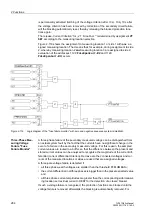
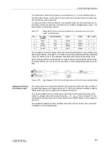
7UT613/63x this applies to forward power supervision P< and the undervoltage pro-
tection.
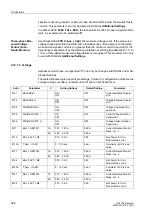
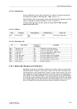
2.19.1.4 Setting Notes
Measured Value
Monitoring
The sensitivity of the measured value monitoring can be changed. Default values are
set at the factory, which are sufficient in most cases. If especially high operating asym-
metry in the currents and/or voltages is to be expected for the application, or if it
becomes apparent during operation that certain monitoring functions activate sporad-
ically, then the setting should be less sensitive.
The current symmetry supervision can be switched
ON
or
OFF
in address
8101
BALANCE I
, the voltage supervision (if available) in address
8102
BALANCE U
.
The current phase sequence can be switched
ON
or
OFF
in address
8105
PHASE
ROTAT. I
; the voltage sequence monitoring (if available) in address
8106
PHASE
ROTAT. U
.
In address
8104
SUMMATION U
the voltage sum monitoring
ON
or
OFF
can be set (if
available).
Address
8111
BAL. I LIMIT M1
determines the threshold current for measuring
location 1 above which the current balance supervision is effective. Address
8112
BAL. FACT. I M1
is the associated symmetry factor; that is, the slope of the sym-
metry characteristic curve. In order to avoid activation during short-term asymmetries,
the monitoring is delayed at address
8113
T Sym. I th. M1
. This parameter can
only be set with DIGSI at
Additional Settings
. The time delay usually amounts to a
few seconds.
The same considerations apply for the further measuring locations, as far as they are
available and allocated:
Address
8121
BAL. I LIMIT M2
,
8122
BAL. FACT. I M2
and
8123
T Sym. I
th. M2
for measuring location 2,
address
8131
BAL. I LIMIT M3
,
8132
BAL. FACT. I M3
and
8133
T Sym. I
th. M3
for measuring location 3,
address
8141
BAL. I LIMIT M4
,
8142
BAL. FACT. I M4
and
8143
T Sym. I
th. M4
for measuring location 4,
address
8151
BAL. I LIMIT M5
,
8152
BAL. FACT. I M5
and
8153
T Sym. I
th. M5
for measuring location 5.
Address
8161
BALANCE U-LIMIT
determines the threshold voltage above which the
voltage balance supervision is effective. Address
8162
BAL. FACTOR U
is the asso-
ciated symmetry factor, i.e. the slope of the symmetry characteristic curve (if voltages
available). In order to avoid activation during short-term asymmetries, the monitoring
is delayed at address
8163
T BAL. U LIMIT
. This parameter can only be set with
DIGSI at
Additional Settings
. The time delay usually amounts to a few seconds.
In address
8401
BROKEN WIRE
the broken wire monitoring can be enabled or dis-
abled.
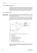
Asymmetrical mea-
sured voltage
failure (Fuse-failure
monitor)
The settings for the fuse failure monitor for single-phase measuring voltage failure (ad-
dress
8426
FFM U<max (3ph)
) are to be selected so that reliable activation occurs
if a phase voltage fails and no false activation occurs during ground faults. Addresses
8422
FFM I< M1
,
8423
FFM I< M2
and
8424
FFM I< M3
must be set for the re-
Содержание SIPROTEC 7UT613 series
Страница 16: ...Contents 16 7UT613 63x Manual C53000 G1176 C160 2 Literature 631 Glossary 623 Index 633 ...
Страница 30: ...1 Introduction 30 7UT613 63x Manual C53000 G1176 C160 2 ...
Страница 506: ...A Appendix 506 7UT613 63x Manual C53000 G1176 C160 2 7UT633 D E ...
Страница 508: ...A Appendix 508 7UT613 63x Manual C53000 G1176 C160 2 7UT633 P Q ...
Страница 510: ...A Appendix 510 7UT613 63x Manual C53000 G1176 C160 2 7UT635 D E ...
Страница 512: ...A Appendix 512 7UT613 63x Manual C53000 G1176 C160 2 7UT635 P Q ...
Страница 515: ...A 2 Terminal Assignments 515 7UT613 63x Manual C53000 G1176 C160 2 7UT633 B ...
Страница 516: ...A Appendix 516 7UT613 63x Manual C53000 G1176 C160 2 7UT633 B Figure A 7 General diagram 7UT633 panel surface mounting ...
Страница 517: ...A 2 Terminal Assignments 517 7UT613 63x Manual C53000 G1176 C160 2 7UT633 N ...
Страница 518: ...A Appendix 518 7UT613 63x Manual C53000 G1176 C160 2 7UT633 N Figure A 8 General diagram 7UT633 panel surface mounting ...
Страница 519: ...A 2 Terminal Assignments 519 7UT613 63x Manual C53000 G1176 C160 2 7UT635 B ...
Страница 520: ...A Appendix 520 7UT613 63x Manual C53000 G1176 C160 2 7UT635 B Figure A 9 General diagram 7UT635 panel surface mounting ...
Страница 521: ...A 2 Terminal Assignments 521 7UT613 63x Manual C53000 G1176 C160 2 7UT635 N ...
Страница 522: ...A Appendix 522 7UT613 63x Manual C53000 G1176 C160 2 7UT635 N Figure A 10 General diagram 7UT635 panel surface mounting ...
Страница 622: ...A Appendix 622 7UT613 63x Manual C53000 G1176 C160 2 ...
Страница 632: ...Literature 632 7UT613 63x Manual C53000 G1176 C160 2 ...


