background image

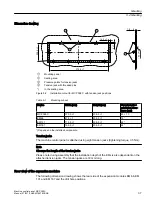
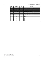
Dimension drawings

Machine control panel: MCP 398C

34

Manual, 07/2018, A5E43199783B AB

Содержание SINUMERIK 840 sl

Страница 1: ...tem SINUMERIK 840D sl 840DE sl 07 2018 A5E43199783B AB Fundamental safety instructions 1 Description 2 Operator control and display elements 3 Dimension drawings 4 Mounting 5 Connecting 6 Service and maintenance 7 Diagnostics 8 Technical data 9 Spare parts accessories 10 Safety symbols 11 ...

Страница 2: ...hose who based on their training and experience are capable of identifying risks and avoiding potential hazards when working with these products systems Proper use of Siemens products Note the following WARNING Siemens products may only be used for the applications described in the catalog and in the relevant technical documentation If products and components from other manufacturers are used thes...

Страница 3: ...put output images 21 2 4 Rating plate 24 3 Operator control and display elements 27 3 1 Front side 27 3 2 Rear side 30 4 Dimension drawings 33 5 Mounting 35 5 1 Introduction 35 5 2 Mounting 36 6 Connecting 39 6 1 Pin assignment of the interfaces 39 6 1 1 Power supply 39 6 1 2 Ethernet ports X20 X21 39 6 1 3 Axis override switches X30 X31 X32 40 6 1 4 Universal inputs X51 X52 X55 41 6 1 5 Universal...

Страница 4: ... 1 3 RI suppression measures 59 9 1 4 SINUMERIK_SouthKorea_Note 60 9 2 Standards and approvals 61 9 3 Recycling and disposal 61 10 Spare parts accessories 63 10 1 Overview 63 10 2 Handwheel connection 64 11 Safety symbols 65 Index 67 Table of contents Machine control panel MCP 398C 4 Manual 07 2018 A5E43199783B AB ...

Страница 5: ... any of the power connections and the protective conductor connection 5 Check whether the existing auxiliary supply circuits are de energized 6 Ensure that the motors cannot move 7 Identify all other dangerous energy sources e g compressed air hydraulic systems or water Switch the energy sources to a safe state 8 Check that the correct drive system is completely locked After you have completed the...

Страница 6: ...there is no ground connection For missing or incorrectly implemented protective conductor connection for devices with protection class I high voltages can be present at open exposed parts which when touched can result in death or severe injury Ground the device in compliance with the applicable regulations WARNING Spread of fire from built in devices In the event of fire outbreak the enclosures of...

Страница 7: ...ed minimum clearance as ventilation clearance for the respective component WARNING Unexpected movement of machines caused by inactive safety functions Inactive or non adapted safety functions can trigger unexpected machine movements that may result in serious injury or death Observe the information in the appropriate product documentation before commissioning Carry out a safety inspection for func...

Страница 8: ...ist strap Wearing ESD shoes or ESD grounding straps in ESD areas with conductive flooring Only place electronic components modules or devices on conductive surfaces table with ESD surface conductive ESD foam ESD packaging ESD transport container 1 3 Warranty and liability for application examples Application examples are not binding and do not claim to be complete regarding configuration equipment...

Страница 9: ... or network segmentation are in place For additional information on industrial security measures that may be implemented please visit Industrial security http www siemens com industrialsecurity Siemens products and solutions undergo continuous development to make them more secure Siemens strongly recommends that product updates are applied as soon as they are available and that the latest product ...

Страница 10: ...ollowing residual risks emanating from the control and drive components of a drive system 1 Unintentional movements of driven machine or system components during commissioning operation maintenance and repairs caused by for example Hardware and or software errors in the sensors control system actuators and cables and connections Response times of the control system and of the drive Operation and o...

Страница 11: ...metal replacement joints etc if they are too close 5 Release of environmental pollutants or emissions as a result of improper operation of the system and or failure to dispose of components safely and correctly 6 Influence of network connected communication systems e g ripple control transmitters or data communication via the network For more information about the residual risks of the drive syste...

Страница 12: ...Fundamental safety instructions 1 5 Residual risks of power drive systems Machine control panel MCP 398C 12 Manual 07 2018 A5E43199783B AB ...

Страница 13: ...c adaptations The key caps can be freely inscribed using a laser Alternatively you can use clear key covers The machine control panel is easy to mount on the rear using special tension jacks The MCP 398C is available as a standard version and with expansion modules Validity The following description applies to the following machine control panels and expansion modules Table 2 1 Standard version De...

Страница 14: ...verse override rotary switch with 23 positions Keyswitch four positions and three different keys Emergency stop button two contact blocks one NO contact one NC contact each Interfaces Two Ethernet interfaces transmission rate 10 100 Mbit s for IE and PN 9 customer specific inputs e g for pushbuttons Six customer specific outputs Connection for two handwheels Sub D Velocity input and contour handwh...

Страница 15: ...ext to the MCP 398C this results in a total width of 585 mm The EM 187 is therefore suitable for use with the SIMATIC IPC 477E 24 Eight 16 mm or 22 mm slots depending on the size of the switching elements Space for the integration for example of pushbuttons a USB interface an Ethernet interface a handwheel an additional override switch or other operator controls Note No built in elements are equip...

Страница 16: ...connection to the 24 VDC connector Flame resistance of the 24 VDC cable in accordance with UL 2556 VW 1 or tested in accordance with IEC 60332 1 2 Observe the permissible bending radius of the cables Only rotate the panel in a way that does not cause pinching of the cables Route all of the cables in such a way that they do not come into contact with chafing edges Note Warning for areas subject to ...

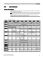
Страница 17: ...The two switches S1 9 and S1 10 must be set to on for the PN functionality The switches S1 1 to S1 8 define the default device name Up to 128 default device names are possible If these default device names are used there is no need for initialization of the MCP Note Reconfiguration of preset device names not possible You cannot reconfigure preset device names for example with STEP 7 Device initial...

Страница 18: ...ff on on on off Default device name mcp pn115 off on off off on on on off Default device name mcp pn114 on off off off on on on off Default device name mcp pn113 off off off off on on on off Default device name mcp pn112 x x x x x x x x on on on on off off off off Default device name mcp pn15 off on on on off off off off Default device name mcp pn14 on off on on off off off off Default device name...

Страница 19: ...10 Meaning off off on on on on on on on on MCP address 255 x x x x x x x x on on on on on off on on MCP address 223 off on on on on off on on MCP address 222 on off on on on off on on MCP address 221 off off on on on off on on MCP address 220 on on off on on off on on MCP address 219 off on off on on off on on MCP address 218 on off off on on off on on MCP address 217 off off off on on off on on M...

Страница 20: ...on on MCP address 194 on off off off off off on on MCP address 193 off off off off off off on on MCP address 192 x x x x x x x x on off off off off off off off MCP address 001 off off off off off off off off MCP address 000 You can find the settings for the basic PLC program in Function Manual Basic Functions P3 sl Switch S2 The handwheel signal type is set with switch S2 1 Table 2 7 Settings of s...

Страница 21: ...p Feed start Feed stop NC start NC stop Position 0 Position 2 EB n 3 RESET Key operat ed switch position 1 Single block Feed override E 24 D 23 C 22 B 21 A 20 EB n 4 Arrow keys Key operat ed switch position 3 Axis selection R15 R13 Rapid tra verse R14 X R1 4th axis R4 7th axis R7 R10 EB n 5 Axis selection Y R2 Z R3 5th axis R5 Motion command in MCS WCS R11 9th axis R9 8th axis R8 6th axis R6 EB n ...

Страница 22: ...ot available to the PLC Table 2 10 MCP 398C output image Byte Bit7 Bit6 Bit5 Bit4 Bit3 Bit2 Bit1 Bit0 AB n 0 Machine function Mode 1000 INC 100 INC 10 INC 1 INC JOG TEACH IN MDA AUTO AB n 1 Feed start Feed stop NC start NC stop Machine function REPOS REF Var INC 10000 INC AB n 2 Arrow key R13 Axis selection Single block Spindle Start Spindle Stop X R1 4th axis R4 7th axis R7 R10 AB n 3 Axis select...

Страница 23: ...1 T12 T13 T14 T15 X R1 Y R2 Z R3 4 R4 5 R5 6 R6 7 R7 8 R8 9 R9 R10 R11 WKS R12 R13 Eilg R14 R15 Sp STOP Sp START VS STOP VS START Figure 2 1 MCP 398C default key assignment Assignment of the inputs I and outputs O to the keys and LEDs QSXWV LQYHUWHG Figure 2 2 Inputs and outputs of the MCP 398C keyboard Description 2 3 Interfaces Machine control panel MCP 398C Manual 07 2018 A5E43199783B AB 23 ...

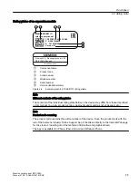
Страница 24: ...VXSSRUW DXWRPDWLRQ VLHPHQV FRP 6XSSO 9 LJLWDO 2XWSXWV 9 3URWHFWLRQ NJ 6 V 7 3 6 180 5 0 3 Component name Material number Serial number Article number Version functional state Product code MAC address Figure 2 3 Example graphic of the MCP 398C rating plate Description 2 4 Rating plate Machine control panel MCP 398C 24 Manual 07 2018 A5E43199783B AB ...

Страница 25: ...e individual rating plate fields on the device may differ from those described in this manual e g new product version approvals and markings not yet issued etc Note Product code scanning The product code contains the article number of the device Scan the product code with the aid of the Siemens Industry Online Support App to be taken directly to the Internet Webpage for the product including all o...

Страница 26: ...Description 2 4 Rating plate Machine control panel MCP 398C 26 Manual 07 2018 A5E43199783B AB ...

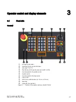
Страница 27: ...s with rapid traverse override R1 to R15 Override switch for the spindle control Spindle control Override switch for the feed control Feed control Slots for two control devices d 16 mm or 22 mm Reset key Keyswitch four positions Figure 3 1 Position of the operator controls on the MCP 398C Machine control panel MCP 398C Manual 07 2018 A5E43199783B AB 27 ...

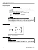
Страница 28: ...om the premature emergency stop unlocking If you have shut down the system to be monitored you can only unlock the emergency stop button or put the system to be monitored back into operation if the condition that triggered the emergency stop function has been corrected and a safe restart is carried out Emergency stop circuit 0 5 1 6723 Figure 3 2 Emergency stop circuit Slots for control devices NO...

Страница 29: ...for turning machines in the accessories pack Key cover Symbol number Key cover Symbol number 7027 7129 7125 7130 7126 7131 7127 7132 7128 You can find the article numbers for the key caps in Section Spare parts accessories Page 63 Operator control and display elements 3 1 Front side Machine control panel MCP 398C Manual 07 2018 A5E43199783B AB 29 ...

Страница 30: ...ion Customer specific inputs Switch S1 Switch S2 Handwheel connection Ethernet 1 EMERGENCY STOP Protective conductor connection Ethernet 2 Customer specific outputs Figure 3 3 Rear of the MCP 398C Operator control and display elements 3 2 Rear side Machine control panel MCP 398C 30 Manual 07 2018 A5E43199783B AB ...

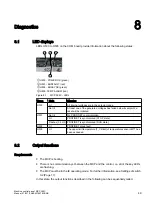
Страница 31: ...OWER OK green H501 BUSFAULT red H502 BUSSYNC green H505 TEMP ALARM red Figure 3 4 MCP 398C LEDs Operator control and display elements 3 2 Rear side Machine control panel MCP 398C Manual 07 2018 A5E43199783B AB 31 ...

Страница 32: ...Operator control and display elements 3 2 Rear side Machine control panel MCP 398C 32 Manual 07 2018 A5E43199783B AB ...

Страница 33: ...m ventilation clearance Figure 4 1 Front and side view of MCP 398C with connection cable For non dimensioned undefined areas a minimum clearance of 0 is permitted Machine control panel MCP 398C Manual 07 2018 A5E43199783B AB 33 ...

Страница 34: ...Dimension drawings Machine control panel MCP 398C 34 Manual 07 2018 A5E43199783B AB ...

Страница 35: ...its with hazardous voltages for the possible individual error scenarios as the basis for dimensioning the protective conductor connection WARNING Electric shock in the event of an individual error when the rear cover is missing If the rear cover is missing when mounting the device in an environment with hazardous voltage a conductor with a hazardous voltage can come loose in the event of a normati...

Страница 36: ...onsibility of the person setting up the system Observe all relevant information from this manual regarding the mounting of the chosen operator panel front The mounting at the installation site is performed in accordance with the instructions of the chosen operator panel front 5 2 Mounting The MCP 398C machine control panel can be combined with the TOP XX00 operator panel fronts as well as with the...

Страница 37: ...1 206 5 1 24 Depends on the installed components Tension jacks The machine control panel is attached using eight tension jacks tightening torque 0 5 Nm Note Observe the length of the tension jacks Please note during assembly that the installation depth of the EMs is also dependent on the attached tension jacks The tension jacks are 30 mm long Rear view of the expansion modules The following dimens...

Страница 38: ...view of the EMs 66 131 and 187 with installation suggestions for the switching elements You can find additional information in the DT configurator on the Internet at https w3 siemens com drives global en engineering commissioning software dt configurator Pages dt configurator aspx https w3 siemens com drives global en engineering commissioning software dt configurator Pages dt configurator aspx Mo...

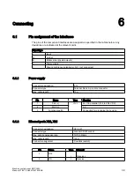
Страница 39: ...or designation X10 Connector type Terminal block 3 pin male connector Max cable length 10 m Pin Name Type Meaning 1 P24 V V 24 VDC potential 20 4 to 28 8 VDC 2 M24 0 V 3 Functional earth Connection for grounding the housing 6 1 2 Ethernet ports X20 X21 Connector designation X20 X21 Connector type Standard RJ45 socket Max data transmission rate 10 100 Mbit s Max cable length 100 m Connector assignm...

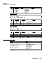
Страница 40: ...alue 16 7 OV_VS8 I Rotary switch position value 8 8 OV_VS4 I Rotary switch position value 4 9 OV_VS2 I Rotary switch position value 2 10 OV_VS1 I Rotary switch position value 1 Spindle override switch Connector designation X31 Connector type Male connector 2 x 5 pin according to IEC603 13 with coding Pin Signal name Type Meaning 1 n c 2 n c 3 M V Ground 4 n c 5 P5 V O Supply 5 V max 100 mA 6 OV_SP...

Страница 41: ... 6 OV_ADD16 I Rotary switch position value 16 7 OV_ADD8 I Rotary switch position value 8 8 OV_ADD4 I Rotary switch position value 4 9 OV_ADD2 I Rotary switch position value 2 10 OV_ADD1 I Rotary switch position value 1 6 1 4 Universal inputs X51 X52 X55 Universal input X51 N N Q 0 0 0 0 0 7 B 1 7 B 1 7 B 1 9 9 9 Figure 6 1 Schematic circuit diagram for X51 Connector designation X51 Connector type ...

Страница 42: ... Connector designation X55 Connector type Male connector 4 pin Pin Signal name Signal type Meaning 1 KT7_IN I Customer key 7 2 KT8_IN I Customer key 8 3 KT9_IN I Customer key 9 4 M V Ground Technical data for digital inputs Parameter Value Voltage Nominal 0 V to 5 V Permissible 3 V to 30 V Typical power consumption 0 2 mA at 5 VDC 0 3 mA at 0 VDC Signal level including ripple High 2 3 V to 5 V Low...

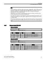
Страница 43: ...wer supply make sure that the fuse used has a tripping rating that corresponds to the maximum possible short term short circuit current of the power supply unit used 6 1 5 Universal outputs X53 X54 Universal output X53 Connector designation X53 Connector type Male connector 4 pin Pin Signal name Type Meaning 1 KT_OUT1 O 24 V output 1 e g lamp for customer key 1 2 KT_OUT2 O 24 V output 2 e g lamp f...

Страница 44: ... name Type Meaning 1 P5HW V O Supply voltage 5 V max 100 mA 2 M V Ground 3 HW1_A I Handwheel pulses track A 4 HW1_XA I Handwheel pulses track A negated 5 n c 6 HW1_B I Handwheel pulses track B 7 HW1_XB I Handwheel pulses track B negated 8 n c 9 P5HW V O Supply voltage 5 V max 100 mA 10 n c 11 M V Ground 12 n c 13 n c 14 n c 15 n c Handwheel 2 Connector designation X61 Connector type 15 pin Sub D s...

Страница 45: ...negated 5 n c 6 HW2_B I Handwheel pulses track B 7 HW2_XB I Handwheel pulses track B negated 8 n c 9 P5HW V O Supply voltage 5 V max 100 mA 10 n c 11 M V Ground 12 n c 13 n c 14 n c 15 n c Connecting 6 1 Pin assignment of the interfaces Machine control panel MCP 398C Manual 07 2018 A5E43199783B AB 45 ...

Страница 46: ...Connecting 6 1 Pin assignment of the interfaces Machine control panel MCP 398C 46 Manual 07 2018 A5E43199783B AB ...

Страница 47: ...ve cleaners Note Avoid damage Do not clean the device using compressed air or steam jets because they can damage it Checking the device In order to prevent foreign bodies or liquids entering the device regularly check the device for the following Ensure that all the housing screws are in place and tight For damage to the housing For damage to the cable cover or cable entry Protect the device from ...

Страница 48: ...rom power Immediately inform qualified personnel to check the function and ensure that the product functions correctly The following signs can indicate a malfunction Unusual or no functioning Unusual heat generation Smoke development Repair Send the device back to the manufacturer for repair The device must only be repaired there Service and maintenance Machine control panel MCP 398C 48 Manual 07 ...

Страница 49: ...nication Lit PROFINET is synchronized STOP state Flashes 0 5 Hz PROFINET is synchronized RUN state H502 Lit PROFINET group fault H505 Lit The upper limit temperature T_Critical of temperature sensor LM77 has been exceeded 8 2 Output functions Requirements The MCP is booting There is no communication yet between the MCP and the control i e all of the key LEDs are flashing The MCP must be in the IE ...

Страница 50: ...played digit for digit as in the following example when the keys are held The sequence is terminated with a dot 1st digit of the SW version 2nd digit of the SW version 3rd digit of the SW version FEED Start and FEED STOP keys Figure 8 2 Activating the SW version output Example SW version V02 02 16 00 1 2 Diagnostics 8 2 Output functions Machine control panel MCP 398C 50 Manual 07 2018 A5E43199783B...

Страница 51: ...3 4 5 6 Diagnostics 8 2 Output functions Machine control panel MCP 398C Manual 07 2018 A5E43199783B AB 51 ...

Страница 52: ...uccession The advance is performed with the SPINDLE START key Hundreds position of the bus address Tens position of the bus address Ones position of the bus address FEED Start FEED STOP and SPINDLE START keys Figure 8 3 Activating the IP address output Example IP address 192 168 214 10 1 2 Diagnostics 8 2 Output functions Machine control panel MCP 398C 52 Manual 07 2018 A5E43199783B AB ...

Страница 53: ...ee Settings of switch S2 Page 17 In this state the operating functions described in the following can be executed in the test mode Test mode Activation Press the RESET key Automatic deactivation No operator control was pressed in the last 3 seconds Manual deactivation Simultaneously press the CYCLE STOP and CYCLE START keys Diagnostics 8 3 Key test Machine control panel MCP 398C Manual 07 2018 A5E...

Страница 54: ...the rotary switch Each time the rotary switch is turned an LED is switched on in sequence in the form of a running light Function of the key operated switch When the key operated switch is turned positions 0 3 are displayed by 0 up to three LEDs Diagnostics 8 3 Key test Machine control panel MCP 398C 54 Manual 07 2018 A5E43199783B AB ...

Страница 55: ...ion max 1 25 A Mechanical data Dimensions W x H x D mm 398 x 225 x 110 4 66 x 225 x 28 131 x 225 x 33 187 x 225 x 33 Weight kg 1 7 0 3 0 5 0 6 Max vertical mounting posi tion 45 Tightening torques max Tension jacks 0 5 Nm M3 0 8 Nm standard M4 1 8 Nm M5 3 Nm standard Mechan stability According to UL 61010 3 Climatic environmental conditions Classification of the climatic environment 3K3 according ...

Страница 56: ...sistance of the material according to UL 94 V 1 and the mechanical stability fire protection requirements touch protection according to UL 61010 4 If power supply units with primary side supplies up to 600 VAC line to neutral voltage have to be deployed the transient voltages on the primary side of the power supply unit must be limited to 4000 V 5 Connect the device only to a 24 VDC power supply t...

Страница 57: ...hnical properties of the emergency stop button are taken into account 9 1 Supplementary electrical conditions 9 1 1 Power supply Requirements for DC power supplies WARNING Electric shock due to connection of an unsuitable power supply When equipment is connected to an unsuitable power supply and or insufficiently grounded or rear cover Page 35 exposed components may carry a hazardous voltage that ...

Страница 58: ...ltage ripple peak peak Ramp up time when switched on 24 VDC 20 4 VDC to 28 8 VDC 5 unsmoothed 6 pulse recti fication any Non periodic overvoltages Period of overvoltage Recover time Events per hour 35 V 500 ms 50 s 10 Transient voltage interruptions Downtime Recovery time Events per hour 3 ms 10 s 10 See also Grounding concept Page 58 9 1 2 Grounding concept Components The SINUMERIK 840D sl system...

Страница 59: ...uidelines 9 1 3 RI suppression measures In addition to the protective grounding of system components special precautions must be taken to ensure safe fault free operation of the system These measures include shielded signal lines special equipotential bonding connections and isolation and shielding measures Shielded signal cables Use the specified cables for safe and fault free operation of the sy...

Страница 60: ... connection of shielded cables can be found in the EMC Installation Guidelines 9 1 4 SINUMERIK_SouthKorea_Note EMC limit values in South Korea The EMC limit values to be complied with for South Korea correspond to the limit values of the EMC product standard for variable speed electric drives EN 61800 3 Category C2 or limit value class A Group 1 according to EN 55011 By applying suitable supplemen...

Страница 61: ...ibility EMC Directive Directive 2011 65 EC on the restriction of the use of certain hazardous substances in electrical and electronic devices RoHS II 9 3 Recycling and disposal Products should be disposed of corresponding to the relevant national regulations The products described in this manual can be mostly recycled due to the fact that they contain very few damaging substances To recycle and di...

Страница 62: ...Technical data 9 3 Recycling and disposal Machine control panel MCP 398C 62 Manual 07 2018 A5E43199783B AB ...

Страница 63: ...ndle dials and rapid traverse 6FC5247 0AF12 1AA0 Override feed rapid traverse Electronic rotary switch 1x23G T 32 cap but ton pointer feed and rapid traverse dials 6FC5247 0AF13 1AA0 Rapid traverse dial 1 set with 20 units for MCP 398C 16 position ro tary switch 6FC5248 0AF30 0AA0 Key caps Square can be labeled with laser 1 set of 90 ergo gray and 20 each of red green yellow medium gray 6FC5248 0A...

Страница 64: ...for emergency stop 10 2 Handwheel connection A connecting cable is available to connect the COM board handwheels see Overview Page 63 1 3LQ LPHQVLRQV LQ PP B B B B 6KLHOG RXVLQJ SODQDWLRQ 6LJQDO FRQQHFWRU 6LJQDO FDEOH 6LJQDO FRQQHFWRU 0 67 3 2 1 Figure 10 1 Connection cable for HHU handwheel Spare parts accessories 10 2 Handwheel connection Machine control panel MCP 398C 64 Manual 07 2018 A5E43199...

Страница 65: ...or for pro tecting against electrical shock in the event of an error or for a connect ing terminal of the external protective conductor Ground For marking the ground connection General warning symbol The documentation must be consulted in any scenario where the sym bol is affixed in order to find out the type of potential hazard and the actions required to avoid the risk Machine control panel MCP ...

Страница 66: ...Safety symbols Machine control panel MCP 398C 66 Manual 07 2018 A5E43199783B AB ...

Страница 67: ...andwheel MCP 398C 14 K Key caps MCP 398C 13 Keyswitch MCP 398C 14 M Maintenance 47 MCP 398C Current consumption 55 EKS identification system 13 Emergency stop button 14 57 Emergency stop circuit 28 Ethernet 14 Handwheel 14 Key caps 13 Keyswitch 14 Mounting position 38 Power consumption 55 MCP 398C Expansion modules 13 Standard version 13 P Potential equalization 59 Protective separation Connection...

Страница 68: ...Index Machine control panel MCP 398C 68 Manual 07 2018 A5E43199783B AB ...

Отзывы: