


4.5.6
Fixed point calibration
If you want to use a fixed point as the reference point in manual measurement of the tool length,
you must first determine the position of the fixed point relative to the machine zero.
Test socket
You can use a mechanical test socket as the fixed point, for example. Mount the test socket
on the machine table in the machining space of the machine. Enter zero as the distance.
Distance gauge
However, you can also use any fixed point on the machine in combination with a distance
gauge. Enter the thickness of the plate as "DZ".
To calibrate the fixed point, use either a tool whose length is known (i.e. the tool length must
be entered in the tool list) or the spindle directly.
The position of the fixed point may have already been determined by the machine
manufacturer.
Machine manufacturer
Please refer to the machine manufacturer's specifications
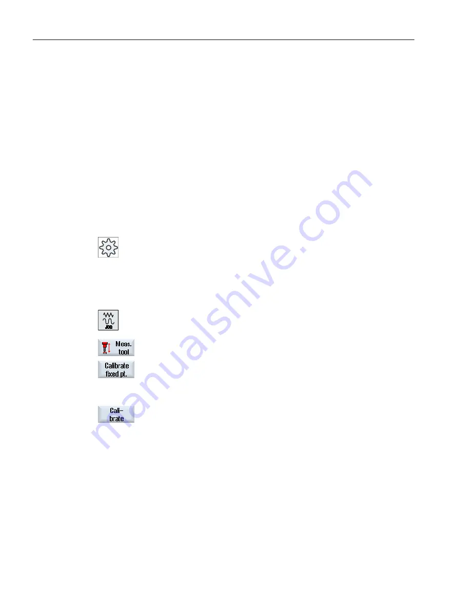
Procedure
1.
Traverse the tool or spindle to the fixed point.
2.
Press the "Measure tool" softkey in the "JOG" mode.
3.
Press the "Calibrate fixed point" softkey.
4.
Enter a correction value for "DZ".
If you have used a distance gauge, enter the thickness of the plate used.
5.
Press the "Calibrate" softkey.
6.
The distance between machine zero and fixed point is calculated and
entered in the machine data.
4.5.7
Measuring the drilling and milling tool length with electrical tool probe
For automatic measurement, you determine the length and radius or diameter of the tool with
the aid of a tool probe (table probe system). The control uses the known positions of the
toolholder reference point and tool probe to calculate the tool offset data.
Use the softkey to select whether you want to measure the length, the radius or the diameter
of the tool.
Setting up the machine
4.5 Measure tool
Milling
104
Operating Manual, 08/2018, 6FC5398-7CP41-0BA0
Содержание SINUMERIK 828D Turning
Страница 68: ...Introduction 2 4 User interface Milling 68 Operating Manual 08 2018 6FC5398 7CP41 0BA0 ...
Страница 162: ...Setting up the machine 4 12 MDA Milling 162 Operating Manual 08 2018 6FC5398 7CP41 0BA0 ...
Страница 270: ...Machining the workpiece 6 17 Setting for automatic mode Milling 270 Operating Manual 08 2018 6FC5398 7CP41 0BA0 ...
Страница 278: ...Swivel combination 45 90 Simulating machining 7 1 Overview Milling 278 Operating Manual 08 2018 6FC5398 7CP41 0BA0 ...
Страница 294: ...Simulating machining 7 9 Displaying simulation alarms Milling 294 Operating Manual 08 2018 6FC5398 7CP41 0BA0 ...
Страница 316: ...Generating a G code program 8 10 Measuring cycle support Milling 316 Operating Manual 08 2018 6FC5398 7CP41 0BA0 ...
Страница 684: ...Collision avoidance 12 2 Set collision avoidance Milling 684 Operating Manual 08 2018 6FC5398 7CP41 0BA0 ...
Страница 746: ...Tool management 13 16 Working with Multitool Milling 746 Operating Manual 08 2018 6FC5398 7CP41 0BA0 ...
Страница 830: ...Alarm error and system messages 15 9 Remote diagnostics Milling 830 Operating Manual 08 2018 6FC5398 7CP41 0BA0 ...
Страница 846: ... Working with Manual Machine 16 7 More complex machining Milling 846 Operating Manual 08 2018 6FC5398 7CP41 0BA0 ...
Страница 870: ...HT 8 840D sl only 18 5 Calibrating the touch panel Milling 870 Operating Manual 08 2018 6FC5398 7CP41 0BA0 ...
Страница 890: ...Easy Message 828D only 20 7 Making settings for Easy Message Milling 890 Operating Manual 08 2018 6FC5398 7CP41 0BA0 ...
Страница 924: ...Edit PLC user program 828D only 23 8 Searching for operands Milling 924 Operating Manual 08 2018 6FC5398 7CP41 0BA0 ...
Страница 925: ...Appendix A A 1 840D sl 828D documentation overview Milling Operating Manual 08 2018 6FC5398 7CP41 0BA0 925 ...


