background image

Connecting 


3.1 Interface overview 


Electrical Installation Manual 

16


Operating Instructions, 12/2014, 6FC5397-2EP10-0BA0 

Legend 

Interface 

Comment 


X21 

FAST I/O 


X301, X302 

Distributed I/O 


X10 

Handwheel inputs 


X60 

Spindle encoder interface 


X54 

Analog spindle interface 


X2 

RS232 interface 


X51, X52, X53 

Pulse drive interfaces 


X30 

USB interface, for connection with the MCP 


X1 

Power supply interface, +24V DC power supply 


Battery interface 


Slot for the System CompactFlash Card (CF card) 

Front 


USB interface 


Note 
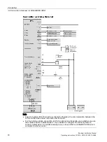
The rated output current of all the digital outputs is 250 mA. 


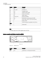
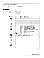
Interface overview on the Machine Control Panel (MCP)  


Figure 3-2 

Interface layout 


Legend 

Interface 

Comment 

Rear 


X10 

USB interface, for connection with the PPU 


Содержание SINUMERIK 808D

Страница 1: ...INUMERIK 808D Electrical Installation Manual Operating Instructions Valid for SINUMERIK 808D Turning software version V4 4 2 SINUMERIK 808D Milling software version V4 4 2 Target group Electrical engineers and electrical assembly workers 12 2014 6FC5397 2EP10 0BA0 Preface Safety instructions 1 System overview 2 Connecting 3 Technical specifications 4 Appendix A ...

Страница 2: ...d only by personnel qualified for the specific task in accordance with the relevant documentation in particular its warning notices and safety instructions Qualified personnel are those who based on their training and experience are capable of identifying risks and avoiding potential hazards when working with these products systems Proper use of Siemens products Note the following WARNING Siemens ...

Страница 3: ...rning Programming and Operating Manual Milling Manual Machine Plus Turning Online Help for Programming and Operating Turning Online Help for Programming and Operating Milling Online Help for Manual Machine Plus Turning My Documentation Manager MDM Under the following link you will find information to individually compile your documentation based on the Siemens content www siemens com mdm Target gr...

Страница 4: ...the number 15257461 as the search term or contact your local Siemens office Licensing provisions The SINUMERIK 808D software is protected by national and international copyright laws and agreements Unauthorized reproduction and distribution of this software or parts thereof is liable to prosecution It will be prosecuted both according to criminal and civil law and may result in severe penalties or...

Страница 5: ... 3 3 6 Pulse drive interfaces X51 X52 X53 30 3 3 7 Analog spindle interface X54 33 3 3 8 Spindle encoder interface X60 35 3 3 9 RS232 interface X2 36 3 3 10 Power supply interface X1 37 3 3 11 USB interface on the front cover of the PPU 38 3 3 12 USB interface X30 38 3 3 13 Battery interface 39 3 3 14 Slot for the system CompactFlash Card CF card 40 3 4 Connecting the USB interface on the MCP 40 4...

Страница 6: ...Table of contents Electrical Installation Manual 6 Operating Instructions 12 2014 6FC5397 2EP10 0BA0 ...

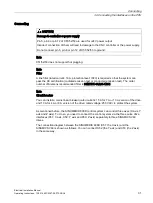
Страница 7: ...manual can result in death severe personal injury or considerable damage to property Without prior authorization you are not allowed to perform any modification on the machine Identification NOTICE Property loss Deliverables received should be complete and intact Exercise caution to ensure that you do not put a damaged device into service Otherwise you may suffer property loss Make sure that the P...

Страница 8: ...or corrosion hazards it contains high risk of fire or electric shock The fire or electric shock may lead to death or serious injury Do install the control system in an area free of inflammables or combustibles water or corrosion hazards Note When dimensioning the control cabinet make sure that the installed components do not exceed the permissible ambient temperature even if the outside temperatur...

Страница 9: ...must be shielded and grounded Commissioning Note Do not forget to back up data after completing the commissioning work Note Clear the manufacturer password before the machine is delivered otherwise end users can start the controller with the standard data which can initialize the SINUMERIK 808D control system As a consequence the machine will not run Carrying out of repairs DANGER Carrying out of ...

Страница 10: ...Safety instructions Electrical Installation Manual 10 Operating Instructions 12 2014 6FC5397 2EP10 0BA0 ...

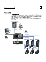
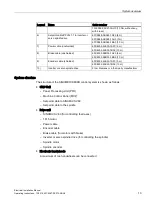
Страница 11: ...t of the control system can control up to two feed axes and one spindle If configured with a software option for the additional axis function it can additionally control an axis that serves as either a rotary axis or a linear axis The milling variant of the control system can control up to three feed axes and one spindle The following diagram shows a system configuration example for the SINUMERIK ...

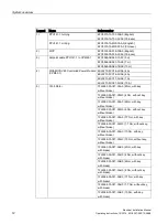
Страница 12: ... 6SL3210 5CC21 0UA0 10 A 5 1FL5 Motor 1FL5060 0AC21 0AA0 4 Nm with key without brake 1FL5060 0AC21 0AG0 4 Nm without key without brake 1FL5062 0AC21 0AA0 6 Nm with key without brake 1FL5062 0AC21 0AG0 6 Nm without key without brake 1FL5064 0AC21 0AA0 7 7 Nm with key without brake 1FL5064 0AC21 0AG0 7 7 Nm without key without brake 1FL5066 0AC21 0AA0 10 Nm with key without brake 1FL5066 0AC21 0AG0 ...

Страница 13: ... 10 m 9 Encoder cable shielded 6FX6002 2LE00 1AF0 5 m 6FX6002 2LE00 1BA0 10 m 10 Inverter or servo spindle drive From Siemens or a third party manufacturer System structure The structure of the SINUMERIK 808D control system is shown as follows CNC Unit Panel Processing Unit PPU Machine Control Panel MCP Setpoint cable to SINAMICS V60 Setpoint cable to the spindle Drive unit SINAMICS V60 for contro...

Страница 14: ...System overview Electrical Installation Manual 14 Operating Instructions 12 2014 6FC5397 2EP10 0BA0 ...

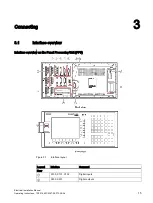
Страница 15: ...nstructions 12 2014 6FC5397 2EP10 0BA0 15 Connecting 3 3 1 Interface overview Interface overview on the Panel Processing Unit PPU Figure 3 1 Interface layout Legend Interface Comment Rear X100 X101 X102 Digital inputs X200 X201 Digital outputs ...

Страница 16: ...rface X2 RS232 interface X51 X52 X53 Pulse drive interfaces X30 USB interface for connection with the MCP X1 Power supply interface 24V DC power supply Battery interface Slot for the System CompactFlash Card CF card Front USB interface Note The rated output current of all the digital outputs is 250 mA Interface overview on the Machine Control Panel MCP Figure 3 2 Interface layout Legend Interface ...

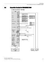
Страница 17: ...Connecting 3 2 Connection Overview for SINUMERIK 808D Electrical Installation Manual Operating Instructions 12 2014 6FC5397 2EP10 0BA0 17 3 2 Connection Overview for SINUMERIK 808D ...

Страница 18: ...ected otherwise the communication between the PPU and the drives does not function as it should For the turning variant connection to X52 is optional and depends upon whether you use the software option additional axis If you desire to configure the control system to control a rotary axis or an additional linear axis connect X52 to a SINAMICS V60 which connects to a servo motor ...

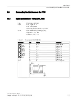
Страница 19: ...on 10 pin Cable Max length 10 m Max cross section One cable per connection 0 5 mm2 Inputs Permissible level including ripple High level 18 V 30 V Low level 3 V 5 V Table 3 1 Pin assignment of X100 DIN0 Illustration Pin Signal Comment 1 N C Not assigned 2 I0 0 Digital input 3 I0 1 Digital input 4 I0 2 Digital input 5 I0 3 Digital input 6 I0 4 Digital input 7 I0 5 Digital input 8 I0 6 Digital input ...

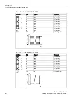
Страница 20: ... 3 I1 1 Digital input 4 I1 2 Digital input 5 I1 3 Digital input 6 I1 4 Digital input 7 I1 5 Digital input 8 I1 6 Digital input 9 I1 7 Digital input 10 M External ground Table 3 3 Pin assignment of X102 DIN2 Interface Pin Signal Comment 1 N C Not assigned 2 I2 0 Digital input 3 I2 1 Digital input 4 I2 2 Digital input 5 I2 3 Digital input 6 I2 4 Digital input 7 I2 5 Digital input 8 I2 6 Digital inpu...

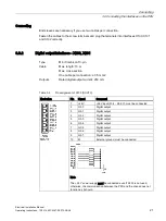
Страница 21: ...length 10 m Max cross section One cable per connection 0 5 mm2 Outputs Rated digital output current 250 mA Table 3 4 Pin assignment of X200 DOUT0 Illustration Pin Signal Comment 1 24V 24V input 20 4 28 8 V must be connected 2 Q0 0 Digital output 3 Q0 1 Digital output 4 Q0 2 Digital output 5 Q0 3 Digital output 6 Q0 4 Digital output 7 Q0 5 Digital output 8 Q0 6 Digital output 9 Q0 7 Digital output ...

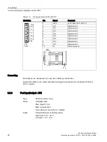
Страница 22: ... output 6 Q1 4 Digital output 7 Q1 5 Digital output 8 Q1 6 Digital output 9 Q1 7 Digital output 10 M External ground Connecting End sleeves are necessary if you use two cables per connection Fasten the cables to the screw terminals and plug the terminals into interfaces X200 and X201 correctly 3 3 3 Fast input output X21 Type Mini Combicon 10 pin Cable Shielded cable Max length 10 m Max cross sect...

Страница 23: ...CRDY_2 NCRDY contact 2 4 DI1 Digital input 5 DI2 Digital input 6 BERO_SPINDLE or DI3 Spindle bero or digital input 7 DO1 Fast output 8 CW Spindle rotating clockwise 9 CCW Spindle rotating counter clockwise 10 M Ground Connecting You can connect the FAST I O to the inverter to control the spindle rotating direction unipolar NC readiness is in the form of a relay contact NO It must be integrated int...

Страница 24: ...y if you use two cables per connection Fasten the cables to the screw terminals and plug the terminal into the interface X21 You can buy the shielded cables from a third party manufacturer 3 3 4 Distributed I O X301 X302 Pin assignment Type 50 pin socket Inputs Permissible level including ripple High level 18 V 30 V Low level 3 V 5 V Outputs Rated digital output current 250 mA ...

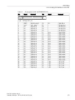
Страница 25: ...tput 9 I3 6 Digital input 34 Q2 3 Digital output 10 I3 7 Digital input 35 Q2 4 Digital output 11 I4 0 Digital input 36 Q2 5 Digital output 12 I4 1 Digital input 37 Q2 6 Digital output 13 I4 2 Digital input 38 Q2 7 Digital output 14 I4 3 Digital input 39 Q3 0 Digital output 15 I4 4 Digital input 40 Q3 1 Digital output 16 I4 5 Digital input 41 Q3 2 Digital output 17 I4 6 Digital input 42 Q3 3 Digita...

Страница 26: ... I7 1 Digital input 37 Q4 6 Digital output 13 I7 2 Digital input 38 Q4 7 Digital output 14 I7 3 Digital input 39 Q5 0 Digital output 15 I7 4 Digital input 40 Q5 1 Digital output 16 I7 5 Digital input 41 Q5 2 Digital output 17 I7 6 Digital input 42 Q5 3 Digital output 18 I7 7 Digital input 43 Q5 4 Digital output 19 I8 0 Digital input 44 Q5 5 Digital output 20 I8 1 Digital input 45 Q5 6 Digital outp...

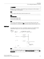
Страница 27: ...QB2 QB3 X302 IB6 IB7 IB8 QB4 QB5 Note The connecting cable between the power source load current supply connection and associated reference potential M must not exceed the maximum permissible length of 10 m Digital inputs The diagram below shows you how to connect the connector pins of the digital inputs at interface X301 example You can connect connector X302 in the same way Note When using an ex...

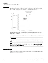
Страница 28: ...st connect an external 24 V DC power supply X301 X302 pins 47 48 49 50 You must also connect the reference ground of the external power supply to X301 X302 Pin 1 MEXT CAUTION You must ensure that the max current consumption at pin 47 pin 48 pin 49 or pin 50 does not exceed 1 A Note You must connect the 24 V power supply for the digital outputs to all the four power input pins X301 X302 pins 47 48 ...

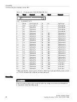
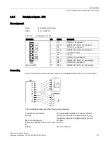
Страница 29: ...E TRACK B handwheel 1 5 5V 5V power output 6 M Ground 7 A2 TRACK A2 handwheel 2 8 A2_N NEGATIVE TRACK A2 handwheel 2 9 B2 TRACK B2 handwheel 2 10 B2_N NEGATIVE TRACK B2 handwheel 2 Connecting You are allowed to connect at most 2 electronic handwheels at connector X10 on the PPU The handwheels must meet the following requirements Transmission procedure 5V square wave signals TTL level or RS422 Sign...

Страница 30: ...o drive side 4 BERO Zero mark from drive side 5 24V POWER from the pin 1 of X200 24V output 6 RST ALARM RESET to drive side 7 M24 Ground 8 24V POWER from the pin 1 of X200 24V output 9 PULSE NEGATIVE PULSE to drive side 10 DIR NEGATIVE DIRECTION to drive side 11 ENA NEGATIVE ENABLE to drive side 12 24V POWER from the pin 1 of X200 24V output 13 M24 Ground 14 RDY DRIVE READY from drive side 15 ALM ...

Страница 31: ...rtification radiated emission test or conducted emission test The order number of Siemens recommended filter is 6SN1111 0AA01 1BA1 Note Circuit breaker You can install a mains linear breaker rated current 15 A for 7 A or 10 A version of the drive and 10 A for 4 A or 6 A version of the drive rated voltage 250 VAC to protect the system As mentioned before the SINUMERIK 808D control system can contro...

Страница 32: ...tructions 12 2014 6FC5397 2EP10 0BA0 The connected motors are SIEMENS 1FL5 servo motors For further information about SINAMICS V60 and 1FL5 servo motors refer to SINUMERIK 808D Mechanical Installation SINAMICS V60 Getting Started or 1FL5 Motor Data sheet See also Analog spindle interface X54 Page 33 ...

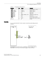
Страница 33: ... to the inverter or servo spindle drive Type 9 pin Sub D female Cable Max length 10m Table 3 10 Pin assignment of connector X54 SPINDLE Illustration Pin Signal Comment 1 AO Analog voltage 2 not assigned 3 not assigned 4 not assigned 5 SE1 Analog drive enable contact electrically isolated n o contact 6 SE2 Analog drive enable contact electrically isolated n o contact 7 not assigned 8 not assigned 9...

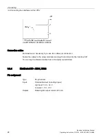
Страница 34: ...ces on the PPU Electrical Installation Manual 34 Operating Instructions 12 2014 6FC5397 2EP10 0BA0 Figure 3 3 Connecting the inverter or the servo spindle drive unipolar Figure 3 4 Connecting the inverter or the servo spindle drive bipolar ...

Страница 35: ...15 pin female Cable Type encoder cable Max length 10m Table 3 11 Pin assignment of X60 SP ENCODER Illustration Pin Signal Comment 1 Not assigned 2 Not assigned 3 Not assigned 4 5V 5 V power supply 5 Not assigned 6 5V 5 V power supply 7 M Ground 8 Not assigned 9 M Ground 10 Z Zero mark 11 Z_N Zero mark negative 12 B_N Track B negative 13 B Track B 14 A_N Track A negative 15 A Track A ...

Страница 36: ...he SINUMERIK 808D via an RS232 port for communication purposes Type Sub D 9 pin male Cable Type RS232 Max length 10m Table 3 12 Pin assignment of X2 RS232 Illustration Pin Signal name Signal type Comment 1 Not assigned 2 RxD I Receive Data 3 TxD O Transmit Data 4 DTR O Data Terminal Ready 5 M VO Ground 6 DSR I Request Set Ready 7 RTS O Request To Send 8 CTS I Clear To Send 9 Not assigned ...

Страница 37: ...connector casing on the side of the control system The cable set offered as accessories provides maximum interference immunity 3 3 10 Power supply interface X1 The SINUMERIK 808D uses a DC 24 V power supply You can connect the DC 24V power supply via interface X1 Type Combicon 4 pin Cable Max length 10m Table 3 13 Pin assignment of X1 Illustration Pin1 Signal Name Comment 1 0 V M24 0 V 2 24 V P24 ...

Страница 38: ...type Comment 1 P5_USB0 VO 5V power supply 2 DM_USB0 I O USB data 3 DP_USB0 I O USB data 4 M VO Ground 3 3 12 USB interface X30 There is a USB interface at the back cover of the PPU This USB interface is used for connection with the MCP Type USB socket type A Combicon 7 pin Cable Type USB cable Max length 0 5 m Table 3 14 Pin assignment of X30 MCP Illustration Pin Signal name Signal type Comment 1 ...

Страница 39: ...y connector into the battery interface by yourself before switching the controller on You can access it after removing the maintenance door Maintenance door Battery interface Battery Battery connector Note When connecting the battery ensure that the tab on the connector faces the battery otherwise the alarm NCK battery alarm will be output after you switch on the controller and you could lose your...

Страница 40: ...Note Do not touch or remove the system CompactFlash Card CF card under any conditions 3 4 Connecting the USB interface on the MCP The machine control panel MCP is connected to the operator panel PPU via a USB cable You can find the USB cable in the MCP package Pin assignment Designation X10 Type USB socket type B Combicon 4 pin Cable Max length 0 3m Table 3 15 Pin assignment of X10 NC Illustration...

Страница 41: ...t 2 A 0 5 A Power loss max 50 W max 5 W Interference immunity in accordance with EN 61800 3 20 μs 20 μs Overvoltage category 3 3 Degree of pollution 2 2 Transport and storage conditions Temperature 20 C to 60 C 20 C to 60 C Vibration resistance transport 5 Hz 9 Hz 3 5 mm 9 Hz 200 Hz 1g 5 Hz 9 Hz 3 5 mm 9 Hz 200 Hz 1g Shock resistance transport 10 g peak value 6 ms duration 100 shocks in each of th...

Страница 42: ... 950 mAh Life time 3 years Certificate CE CE 4 1 Radio interference Table 4 1 Limit values for radio interference suppression in industrial environments Limit class according to EN61800 3 Conducted radio interference C3 Radio interference C3 Note You must consider interference radiation for the complete system Particular attention should be paid to cabling Contact your sales representative for ass...

Страница 43: ...ve Devices Modules are commonly abbreviated ESD The common international designation ESD stands for Electrostatic Sensitive Device Electrostatic sensitive modules are identified by the following symbol CAUTION Electrostatic sensitive devices may be destroyed by voltages that are undetectable to a human Voltages of this kind occur as soon as a component or an assembly is touched by a person who is ...

Страница 44: ...a person A 1 3 Basic protective measures against discharge of static electricity Make sure the grounding is good When working with electrostatically sensitive devices make sure that the person the workstation and the packaging are properly grounded which helps you avoid static charge Avoid direct contact You should only touch ESD components if this is unavoidable for example during maintenance wor...

Страница 45: ... m 6FC5548 0BA05 1BA0 Spare parts Battery 6FC5247 0AA18 0AA0 Options Software MM for turning only 6FC5800 0AP07 0YB0 Additional axis for turning only 6FC5800 0AK70 0YB0 Toolbox 6FC5811 0CY00 0YA8 Documentation Operating Instructions English 6FC5397 2EP10 0BA0 Chinese 6FC5397 2EP10 0RA0 Diagnostics Manual English 6FC5398 6DP10 0BA0 Chinese 6FC5398 6DP10 0RA0 Commissioning Manual English 6FC5397 4EP...

Страница 46: ...t at the digital output interfaces Answer Check whether you have connected the 24 V DC power supply or not Check PLC signals FAQ 2 Black screen Answer Check whether you have correctly connected the 24 V DC power supply or not Check whether you have correctly plugged the battery connector or not Check whether the CF card looses or not ...

Страница 47: ...9 X1 power supply interface 37 X10 handwheel inputs 29 X10 NC 40 X100 19 X101 20 X102 20 X2 RS232 36 X200 21 X201 22 X21 23 X30 MCP 38 X301 25 X302 26 X60 SP ENCODER 35 Interface overview on the Machine Control Panel MCP 16 Interface overview on the Panel Processing Unit PPU 15 P Pin assignment of connector X54 SPINDLE 33 S Safety instructions 7 System overview 11 ...

Страница 48: ...Index Electrical Installation Manual 48 Operating Instructions 12 2014 6FC5397 2EP10 0BA0 ...

Отзывы: