background image


Installing/mounting 


4.2 EMC-compliant installation of a machine or system 

Power Module PM240-2 
Hardware Installation Manual, 01/2017, A5E33294624B AE 

23


4.2


EMC-compliant installation of a machine or system 

The inverter is designed for operation in industrial environments where strong 

electromagnetic fields are to be expected. 
Reliable and disturbance-free operation is only guaranteed for EMC-compliant installation. 
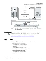
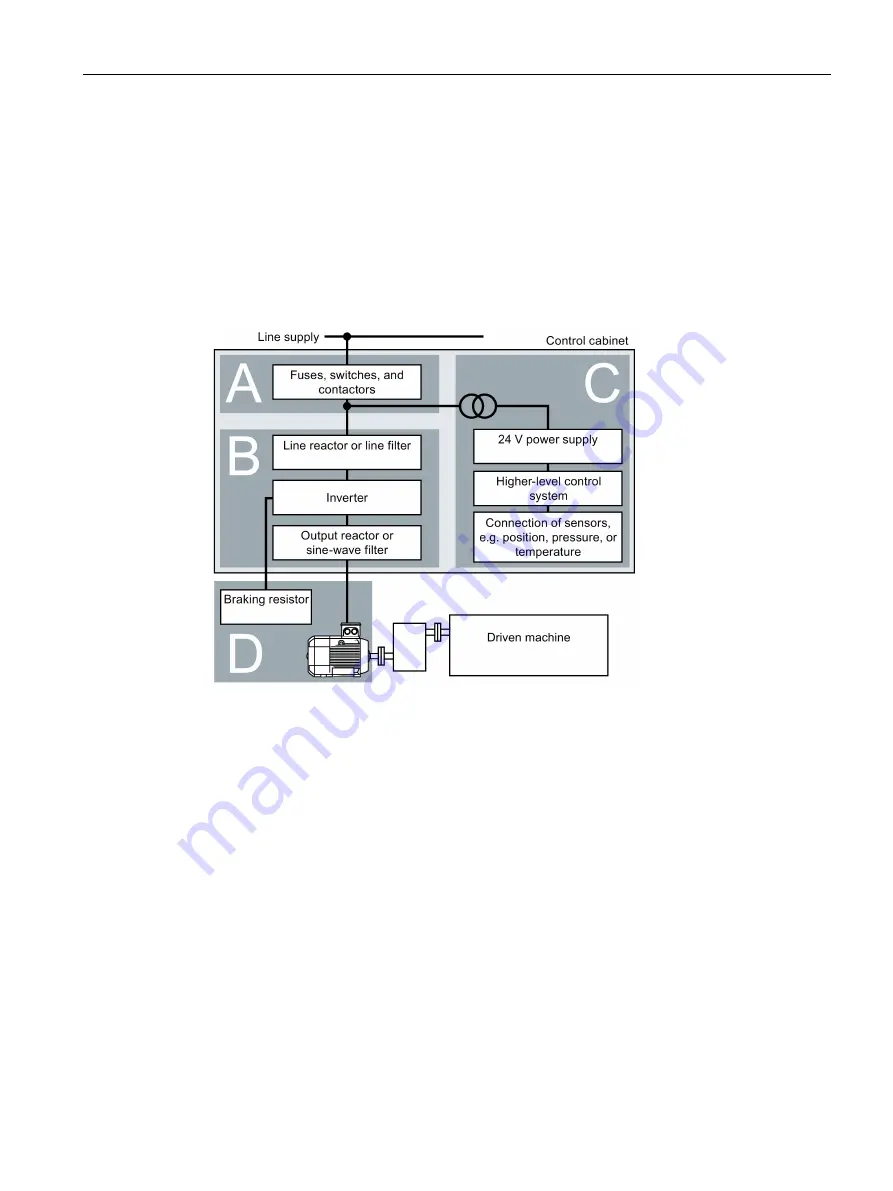
To achieve this, subdivide the control cabinet and the machine or system into EMC zones: 

EMC zones 


Figure 4-1 

Example of the EMC zones of a plant or machine 

Inside the control cabinet 


Zone A: Line supply connection 


Zone B: Power electronics 
Devices in Zone B generate energy-rich electromagnetic fields. 


Zone C: Control and sensors 
Devices in Zone C do not generate any energy-rich electromagnetic fields themselves, 

but their functions can be impaired by electromagnetic fields. 

Outside the control cabinet 


Zone D: Motors, braking resistors 
Devices in Zone D generate electromagnetic fields with a significant amount of energy 

Содержание SINAMICS PM240-2

Страница 1: ......

Страница 2: ......

Страница 3: ...___________ ___________________ ___________________ SINAMICS SINAMICS G120 Power Module PM240 2 Hardware Installation Manual 01 2017 01 2017 A5E33294624B AE Changes in this manual 1 Fundamental safety instructions 2 Introduction 3 Installing mounting 4 Connecting up 5 Service and maintenance 6 Technical data 7 Spare parts 8 Accessories 9 Appendix A ...

Страница 4: ... only by personnel qualified for the specific task in accordance with the relevant documentation in particular its warning notices and safety instructions Qualified personnel are those who based on their training and experience are capable of identifying risks and avoiding potential hazards when working with these products systems Proper use of Siemens products Note the following WARNING Siemens p...

Страница 5: ...uirements 29 4 4 Mounting the Power Modules 31 4 4 1 Dimension drawings and drilling dimensions for built in units IP20 devices 33 4 4 2 Hoisting gear FSD FSF 35 4 4 3 Mounting the shield plate for built in units 35 4 4 4 Dimension drawings and drilling dimensions for PT Power Modules 38 4 4 5 Mounting the shield plate for PT Power Modules 39 4 5 Additional components 39 5 Connecting up 41 5 1 Per...

Страница 6: ...1 7 6 3 Current derating depending on the pulse frequency 400 V inverters 87 7 7 Technical data 690 V inverters 88 7 7 1 General data 690 V inverters 88 7 7 2 Specific technical data 690 V inverters 90 7 7 3 Current derating depending on the pulse frequency 690 V inverters 92 7 8 Restrictions for special ambient conditions 93 7 9 Electromagnetic compatibility of variable speed drives 96 7 9 1 Inve...

Страница 7: ...necting the brake relay 124 9 7 Output reactor 125 9 8 Voltage limiter and du dt filter 130 A Appendix 133 A 1 Manuals and technical support 133 A 1 1 Manuals for your inverter 133 A 1 2 Configuring support 134 A 1 3 Product Support 135 A 2 Disposal 136 A 3 Directives and standards 137 A 4 Abbreviations 139 Index 141 ...

Страница 8: ...Table of contents Power Module PM240 2 8 Hardware Installation Manual 01 2017 A5E33294624B AE ...

Страница 9: ...n section has been revised and moved to the Installation mounting chapter It now has the title EMC compliant installation of a machine or system The Installing Power Modules section has been revised The Connecting chapter has been restructured Connecting the motor to the inverter in a star or delta connection section has been revised The Technical data chapter has been revised and restructured ...

Страница 10: ...Changes in this manual Power Module PM240 2 10 Hardware Installation Manual 01 2017 A5E33294624B AE ...

Страница 11: ... phase conductor and phase conductor to protective conductor Check whether the existing auxiliary supply circuits are de energized Ensure that the motors cannot move 3 Identify all other dangerous energy sources e g compressed air hydraulic systems or water 4 Isolate or neutralize all hazardous energy sources by closing switches grounding or short circuiting or closing valves for example 5 Secure ...

Страница 12: ...sing potential WARNING Danger to life due to electric shock when not grounded For missing or incorrectly implemented protective conductor connection for devices with protection class I high voltages can be present at open exposed parts which when touched can result in death or severe injury Ground the device in compliance with the applicable regulations WARNING Danger to life due to electric shock...

Страница 13: ...he device by another equivalent measure in such a way that contact with fire is prevented Ensure that smoke can only escape via controlled and monitored paths WARNING Danger to life from electromagnetic fields Electromagnetic fields EMF are generated by the operation of electrical power equipment such as transformers converters or motors People with pacemakers or implants are at particular risk in...

Страница 14: ...vere injury or even death This can also result in increased downtime and reduced service lives for devices systems Ensure compliance with the specified minimum clearance as ventilation clearance for the respective component WARNING Danger of an accident occurring due to missing or illegible warning labels Missing or illegible warning labels can result in accidents involving death or serious injury...

Страница 15: ...mentation before commissioning Carry out a safety inspection for functions relevant to safety on the entire system including all safety related components Ensure that the safety functions used in your drives and automation tasks are adjusted and activated through appropriate parameterizing Perform a function test Only put your plant into live operation once you have guaranteed that the functions r...

Страница 16: ...or electrostatic discharge can cause malfunctions through damaged individual components integrated circuits modules or devices Only pack store transport and send electronic components modules or devices in their original packaging or in other suitable materials e g conductive foam rubber of aluminum foil Only touch components modules and devices when you are grounded by one of the following method...

Страница 17: ...ustrial security please visit Industrial security http www siemens com industrialsecurity Siemens products and solutions undergo continuous development to make them more secure Siemens strongly recommends to apply product updates as soon as available and to always use the latest product versions Use of product versions that are no longer supported and failure to apply latest updates may increase c...

Страница 18: ...age X ray ionizing radiation and cosmic radiation 2 Unusually high temperatures including open flames as well as emissions of light noise particles gases etc can occur inside and outside the components under fault conditions caused by for example Component failure Software errors Operation and or environmental conditions outside the specification External influences damage 3 Hazardous shock voltag...

Страница 19: ...e Power Modules You can operate the Power Modules with a Control Unit from one of the following listed families CU230P 2 CU240B 2 CU240E 2 CU250S 2 For Power Modules FSA FSC you require a Control Unit with firmware version V4 4 or higher For Power Modules FSD FSF you require a Control Unit with firmware version V4 7 HF8 or higher Note Commissioning the inverter You must first commission the invert...

Страница 20: ...ble motors Note Motors for inverter operation Only use motors that are suitable for operation with inverters with a DC link Motors for 200 V Power Modules For the 200 V Power Modules induction motors are permissible in the range from 25 150 of the inverter power without any restrictions Motors for 400 V Power Modules For the 400 V Power Modules induction motors are permissible in the range from 25...

Страница 21: ...pliance with EMC regulations EMC compliant installation of a machine or system Page 23 Inverters for systems in the United States Canada UL cUL For a system configuration in conformance with UL cUL use the fuse types approved for UL cUL specified in the Technical data or the circuit breakers under the following Internet address Fuse types Technical data Page 65 Circuit breaker https support indust...

Страница 22: ...0 V inverters 480 V phase with respect to ground 480 V phase to phase for 400 V inverters Terminal voltage VPR 2000 V Suitable for SPD applications type 1 or type 2 Alternatively use a surge protection device article number 5SD7 424 1 from Siemens AG Additional requirements relating to CSA conformance frame sizes FSD FSF Overvoltage category OVC III must be ensured for all connections of the power...

Страница 23: ...To achieve this subdivide the control cabinet and the machine or system into EMC zones EMC zones Figure 4 1 Example of the EMC zones of a plant or machine Inside the control cabinet Zone A Line supply connection Zone B Power electronics Devices in Zone B generate energy rich electromagnetic fields Zone C Control and sensors Devices in Zone C do not generate any energy rich electromagnetic fields t...

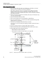
Страница 24: ...ed out of the control cabinet Connect the PE bar and the shield support to the control cabinet frame through a large surface area to establish a good electrical connection Mount the control cabinet components on a bare metal mounting plate Connect the mounting plate to the control cabinet frame and PE bar and shield support through a large surface area to establish a good electrical connection For...

Страница 25: ...llation is available in the Internet EMC installation guideline https support industry siemens com cs ww de view 60612658 en 4 2 2 Cables Cables with a high level of interference and cables with a low level of interference are connected to the inverter Cables with a high level of interference Cable between the line filter and inverter Motor cable Cable at the inverter DC link connection Cable betw...

Страница 26: ...and cables with a low level of interference may only cross over at right angles Keep all of the cables as short as possible Route all of the cables close to the mounting plates or cabinet frames Route signal and data cables as well as the associated equipotential bonding cables parallel and close to one another Twist incoming and outgoing unshielded individual conductors Alternatively you can rout...

Страница 27: ...rter motor cable Cable between the inverter and braking resistor Signal and data cables Connect the motor cable shield to the motor enclosure using a PG gland that establishes a good electrical connection Requirements relating to shielded cables Use cables with finely stranded braided shields Connect the shield to at least one end of the cable Figure 4 4 Examples for EMC compliant shield support A...

Страница 28: ...romechanical components Radio interference suppression Connect interference suppression elements to the following components Coils of contactors Relays Solenoid valves Motor holding brakes Connect the interference suppression element directly at the coil Use RC elements or varistors for AC operated coils and freewheeling diodes or varistors for DC operated coils ...

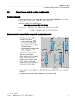
Страница 29: ...erature rise in the control cabinet Measures in order to ensure that the components are adequately cooled Add the power losses of the individual components Power Module data Technical data Page 65 The Control Unit power loss is less than 0 04 kW Use the manufacturers data for components for example reactors or filters Calculate the air flow required using the formula above Ensure that the control ...

Страница 30: ...624B AE Power loss for Power Modules with push through technology PT devices When you use PT Power Modules the majority of the power loss is dissipated through the heatsink located outside the control cabinet The following losses occur in the cabinet when the device is operated with its rated data FSA 0 02 kW FSB 0 045 kW FSC 0 075 kW ...

Страница 31: ...n against condensation or electrically conductive contamination Protect the device e g by installing it in a control cabinet with degree of protection IP54 according to IEC 60529 or NEMA 12 Further measures may be necessary for particularly critical operating conditions If condensation or conductive pollution can be excluded at the installation site a lower degree of control cabinet protection may...

Страница 32: ...t a Power Module in push through technology in a control cabinet The mounting frames include the necessary seals and frames to ensure compliance with degree of protection IP55 If you do not use the optional mounting frames then you must ensure that the required degree of protection is complied with using other appropriate measures Mounting instructions are provided in the following section Mountin...

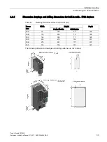
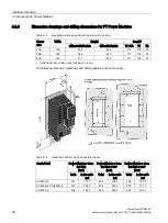
Страница 33: ... and drilling dimensions for built in units IP20 devices Table 4 1 Mounting dimensions without Control Unit mm Frame size Width Height Depth Power Module Shield plate FSA 73 196 80 165 FSB 100 292 78 165 FSC 140 355 77 165 FSD 200 472 152 237 FSE 275 551 177 237 FSF 305 708 257 357 The following dimension drawings and drilling patterns are not to scale ...

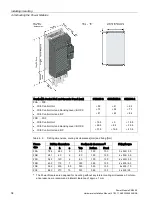
Страница 34: ...ontrol Unit and IOP 15 5 26 5 37 5 0 8 5 19 5 18 5 29 5 40 5 Table 4 2 Drilling dimensions cooling air clearances mm and fixing Nm Frame size Drilling dimensions Cooling air clearances 1 Fixing torque h b c Top Bottom Front FSA 186 62 3 6 80 100 100 3 x M4 2 5 FSB 281 80 6 80 100 100 4 x M4 2 5 FSC 343 120 6 80 100 100 4 x M5 3 5 FSD 430 170 7 300 350 100 4 x M5 6 0 FSE 509 230 8 5 300 350 100 4 x...

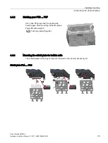
Страница 35: ...624B AE 35 4 4 2 Hoisting gear FSD FSF Use crane lifting lugs and the appropriate hoisting gear when mounting Power Modules Power Module weights Technical data Page 65 4 4 3 Mounting the shield plate for built in units The shield plates and fixings screws are included in the inverter accessory kit Shield plate FSA FSC ...

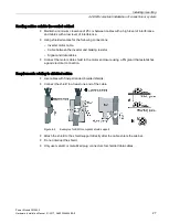
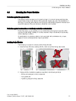
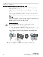
Страница 36: ...cket as described below Note Brake relay If you are using a brake relay to control a motor brake then mount the brake relay at the rear of the lower shield plate before you attach the shield module to the inverter Mounting and connecting the brake relay Page 124 Procedure FSD and FSE Proceed as follows to mount the EMC connecting bracket and the shield plate 1 Attach the EMC connecting bracket to ...

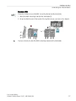
Страница 37: ...4624B AE 37 Procedure FSF Proceed as follows to mount the EMC connecting bracket and the shield plate 1 Attach the EMC connecting bracket to the shield plate 2 Screw the shield module to the inverter using three screws as shown in the diagram You have correctly mounted the EMC connecting bracket and the shield plate ...

Страница 38: ...38 322 171 118 53 FSB 154 345 430 171 118 53 FSC 200 411 500 171 118 53 1 Panel thickness of the control cabinet 3 5 mm The following dimension drawings and drilling patterns are not to scale Table 4 4 Depth with Control Unit and operator panel Control Unit Power Module Con trol Unit mm Power Module Con trol Unit IOP mm Power Module Con trol Unit BOP mm Total in the cabi net Total in the cabi net ...

Страница 39: ... 365 156 80 100 100 10 x M5 3 5 Nm 1 The Power Modules are designed for mounting without any lateral cooling air clearance For toler ance reasons we recommend a lateral clearance of 1 mm 4 4 5 Mounting the shield plate for PT Power Modules The shield plates and fixings screws are included in the inverter accessory kit Figure 4 5 Mounting the shield plate 4 5 Additional components Depending on the ...

Страница 40: ...Installing mounting 4 5 Additional components Power Module PM240 2 40 Hardware Installation Manual 01 2017 A5E33294624B AE ...

Страница 41: ... elapsed Before starting any work check that the system is in a voltage free state by measuring all terminals also to ground Ensure that the associated warning plate in the appropriate language is attached Note Operating displays for inverter operation If when switching over a function from ON to OFF an LED or other similar display is not lit or not active this does not indicate that the device is...

Страница 42: ...f subsequent fault or electric shock Use the protection and monitoring devices recommended in the documentation CAUTION Risk of injury due to hot surfaces During operation and for a short time after the inverter shuts down the surface of the device can reach a high temperature During this time avoid any direct contact with the surface of the inverter WARNING Danger to life through electric shock a...

Страница 43: ... line supply is grounded For inverters with rated input currents 125 A referred to LO use an RCCB type B with a response limit current of 300 mA Connect the RCCB in series with the overcurrent protective devices For inverters with rated input currents 125 A referred to LO use a type B MRCD for example from the Bender company An MRCD comprises an RCM differential current monitoring device a measuri...

Страница 44: ... Restrictions for special ambient conditions Page 93 5 1 1 TN line system A TN line system transfers the PE protective conductor to the installed plant or system using a cable Generally in a TN line system the neutral point is grounded There are versions of a TN system with a grounded line conductor e g with grounded L1 A TN line system can transfer the neutral conductor N and the PE protective co...

Страница 45: ... is either transferred or not Inverter operated on a TT line system Inverter with integrated or external line filter Operation on TT line systems with grounded neutral point permissible Operation on TT line systems without grounded neutral point not permissible Inverter without line filter Operation on all TT line systems permissible For installations in compliance with IEC operation on a TT line ...

Страница 46: ... IT systems with and without trans fer of the neutral conductor N Inverter operated on an IT line system Inverters with integrated line filter Operation on IT line systems not permissible Inverter without line filter Operation on all IT line systems permissible Behavior of the inverter when a ground fault occurs In some instances even for a ground fault the inverter should still remain functional ...

Страница 47: ...ations for protective conductors subject to an increased leakage current at the site of operation Protective conductor for line feeder cables Protective conductor for inverter line feeder cables Protective conductor between PE and the electrical cabinet Protective conductor for motor feeder cables The minimum cross section of the protective conductor depends on the cross section of the line or mot...

Страница 48: ... complete length Cables routed inside electrical cabinets or enclosed machine housings are considered to be adequately protected against mechanical damage As a conductor of a multi conductor cable the protective conductor has a cross section 2 5 mm Cu For an individual conductor the protective conductor has a cross section 10 mm Cu The protective conductor consists of two conductors with the same ...

Страница 49: ... A line reactor is not required for the Power Modules FSD FSF Line filter The inverters are available with or without integrated line filter Class A For frame sizes FSA FSC 3 AC 400 V there are external filters Class B for increased EMC requirements Line filter Page 113 Output reactor An output reactor is not required for the Power Modules FSD FSF Figure 5 2 Block diagram of the inverter FSA FSC F...

Страница 50: ...01 2017 A5E33294624B AE Figure 5 4 Connection to 3 AC 200 V 400 V 690 V Figure 5 5 Connection to 1 AC 200 V only FSA FSC Note Connecting PM240 2 Power Modules 200 V to 1 AC only FSA FSC For the 200 V versions and single phase line systems connect the phase conductor and neutral conductor to any two of the terminals L1 L2 L3 ...

Страница 51: ...tach the cable tie holders to the Power Module as shown to the left in the diagram before you establish the connections Fix the line connecting cable using a cable tie as shown in Fix the shield of the motor connecting cable using a hose clamp Connect the shield of the control cable with the shield plate of the Control Unit using a steel band Also attach the control cable to the Power Module using...

Страница 52: ...vironment Electromagnetic compatibility of variable speed drives Page 96 Table 5 1 Permissible lengths of motor connecting cables inverter FSA FSC EMC category Second Environment C2 No EMC category Inverter with internal C2 filter with external C2 filter with external C1 filter with output reactor without filter without output reac tor without filter with output reactor Cable Shielded Shielded Shi...

Страница 53: ...Modules Inverters Connection Cross section tightening torque Stripped insulation length Metric Imperial FSA Line supply motor DC link and braking resistor Plug connector with screw termi nals 1 5 2 5 mm2 0 5 Nm 16 14 AWG 4 5 lbf in 8 mm FSB 1 5 6 mm2 0 6 Nm 16 10 AWG 5 5 lbf in 8 mm FSC 6 16 mm 1 3 Nm 10 6 AWG 12 lbf in 10 mm FSD Line supply motor and DC link Screw type termi nal 10 35 mm2 2 5 4 5...

Страница 54: ... Power Modules are equipped with with drawable plug connectors that cannot be inad vertently interchanged To remove a plug connector you must release it by pressing on the red lever Release lever Connections for frame sizes FSD FSF You must remove the covers from the con nections in order to connect the line supply braking resistor and motor to the inverter In addition for frame sizes FSD and FSE ...

Страница 55: ... and motor cable at the inverter Power Module PM240 2 Hardware Installation Manual 01 2017 A5E33294624B AE 55 FSD FSE remove the lower covers FSF remove the lower covers Figure 5 6 Connections for the line supply motor and braking resistor ...

Страница 56: ...link or braking resistor Use the rubber cable gland as shown in the right hand figure for connecting the braking resistor Using a sharp knife cut the cap of the cable gland corresponding to the diameter of the connection cable of the braking resistor and establish the con nections An optional shield plate is available as strain relief for the connection cable of the braking resistor Top shield pla...

Страница 57: ...ion if both DIP switches are set to ON Set both DIP switches to OFF if you do not wish to use STO If one switch is set to OFF and the other to ON the inverter signals that the pulses are inhibited and the motor does not start The terminals are low active Further information and wiring examples Manuals for your inverter Page 133 STO connection Use shielded cables with a maximum length of 30 m a cro...

Страница 58: ...ue decreases linearly with 1 f In field weakening the available power remains constant Operating the motor in a delta connection with 87 Hz characteristic In a delta connection the motor is oper ated with a voltage and frequency above its rated values As a consequence the motor power is increased by a factor 3 1 73 In the range f 0 87 Hz the motor can output its rated torque MN The maximum voltage...

Страница 59: ... the inverter and replace defective parts and components to reduce the risk of a fire or an electric shock You must replace the complete overload relay if the current carrying element of the relay has burnt through Repair WARNING Danger due to incorrect repair Repairs may only be carried out by Siemens Service by repair centers authorized by Siemens or by authorized personnel who are thoroughly ac...

Страница 60: ...t regular intervals If necessary remove the air deflection plate at the rear Use a torque of 2 Nm when reconnecting The fans must be installed if you clean the heatsink using water Ventilation The devices must be installed in a cabinet Ensure that the cabinet s ventilation slots are not blocked Check that the fan is functioning correctly Cables and screw terminals Regularly check the cables for da...

Страница 61: ...f the inverter was not operational for longer than one year If the date of manufacture of the inverter was more than one year ago when commissioning the drive system for the first time The date of manufacture is coded in the serial number see the next paragraph You form the DC link capacitors by connecting power to the inverters as shown below Figure 6 1 Forming the DC link capacitors Data of manu...

Страница 62: ...onment can block up the fan The fan must be replaced in good time to ensure that the inverter is ready for operation 6 3 1 Fan replacement FSA FSC Replacing the fan modules for inverters frame sizes FSA FSC Proceed as follows to replace a fan module 1 Switch off the inverter and wait 5 minutes until the DC link capacitors have been discharged 2 Withdraw the line and motor cable plug connectors and...

Страница 63: ...and components Death or serious injury can result when live parts are touched Wait until the discharge time elapses which is stamped on the inverter warning plates and labels 2 Remove the fan unit from the Power Module in steps and as shown in the diagram Use a screwdriver if necessary You have withdrawn the fan unit Installing the fan unit FSD FSF Install the fan unit in the reverse order to what...

Страница 64: ...Service and maintenance 6 3 Replacing a fan Power Module PM240 2 64 Hardware Installation Manual 01 2017 A5E33294624B AE ...

Страница 65: ...view 109486009 7 1 Electromagnetic compatibility Overview Electromagnetic compatibility according to EN61800 3 Property Version Interference immunity The inverters are suitable for use in the first and second industrial environments Interference emission second environment Category C2 for inverters with integrated radio interference suppression filter Category C2 for inverters without filter with ...

Страница 66: ... 1 Ambient conditions in operation Installation altitude Up to 1000 m above sea level without limitations Restrictions for special ambient conditions Page 93 Climatic ambient conditions 1 FSA FSC ambient operating temperature 2 For operation according to Low Overload 10 C 40 C For operation according to High Overload 10 C 50 C Restrictions for special ambient conditions Page 93 FSD FSF ambient ope...

Страница 67: ...gical ambient condi tions Suitable according to 3B1 to EN 60721 3 3 Pollution Suitable for environments with degree of pollution 2 according to EN 61800 5 1 Cooling Forced air cooling AF according to EN 60146 Cooling air Clean and dry air 1 Increased ruggedness regarding temperature range and relative humidity therefore better than 3K3 according to EN 60721 3 3 2 Observe the permissible ambient op...

Страница 68: ...ut current for a Low Overload load cycle LO base load output current Permissible output current for a Low Overload load cycle LO base load power Rated power based on the LO base load output current HO base load input current Permissible input current for a High Overload load cycle HO base load output current Permissible output current for a High Overload load cycle HO base load power Rated power b...

Страница 69: ...lude Pumps fans and compressors Wet or dry blasting technology Mills mixers kneaders crushers agitators Basic spindles Rotary kilns Extruders The High Overload load cycle permits for reduced base load dynamic accelerating phases Typical applications when design ing according to High Overload include Horizontal and vertical conveyor technology conveyor belts roller conveyors chain conveyors Centrif...

Страница 70: ...DC link and braking resistor 1 5 6 mm2 0 6 Nm 16 10 AWG 5 5 lbf in 8 mm FSC Line motor cable DC link and braking resistor 6 16 mm 1 3 Nm 10 6 AWG 12 lbf in 10 mm FSD Line motor cable and DC link 10 35 mm2 2 5 4 5 Nm 20 10 AWG 22 lbf in 8 2 AWG 40 lbf in 18 mm Braking resistor 2 5 16 mm2 1 2 1 5 Nm 20 6 AWG 15 lbf in 10 mm FSE Line motor cable and DC link 25 70 mm2 8 10 Nm 6 3 0 AWG 88 5 lbf in 25 ...

Страница 71: ...Page 44 Line impedance FSA FSC 2 Uk 4 For Uk 2 we recommend a line reactor or a Power Mod ule with the next higher power rating FSD FSF No restrictions Power factor λ FSA FSC 0 7 without line reactor for Uk 2 0 85 with line reactor for Uk 2 FSD FSF 0 95 Output voltage 0 V 0 95 3 ph AC input voltage Input frequency 50 Hz 60 Hz 3 Hz Output frequency 0 550 Hz depending on the control mode Inrush curr...

Страница 72: ...integrated braking chopper Degree of protection ac cording to EN 60529 IP20 IP55 PT devices outside the control cabinet Protection class according to EN 61800 5 1 The inverters are devices with protection class I Touch protection according to EN 50274 DGUV regulation 3 when used for the intended purpose Cooling in compliance with EN 60146 Forced air cooling AF Dependent on the input voltage and ou...

Страница 73: ...se load output current 2 3 A 3 2 A Fuse according to IEC Fuse according to UL class J 3NA3805 16 A 15 A 3NA3805 16 A 15 A Power loss 0 04 kW 0 04 kW Required cooling air flow 5 l s 5 l s Weight without filter 1 4 kg 1 4 kg Weight with filter 1 6 kg 1 6 kg Table 7 3 PM240 2 PT frame size A 1 AC 3 AC 200 V 240 V Article number without filter Article number with filter 6SL3211 1PB13 8UL0 6SL3211 1PB1...

Страница 74: ... 6 A 7 4 A Fuse according to IEC Fuse according to UL class J 3NA3812 32 A 35 A 3NA3812 32 A 35 A 3NA3812 32 A 35 A Power loss 0 05 kW 0 07 kW 0 12 kW Required cooling air flow 9 2 l s 9 2 l s 9 2 l s Weight without filter 2 8 kg 2 8 kg 2 8 kg Weight with filter 3 1 kg 3 1 kg 3 1 kg Table 7 5 PM240 2 PT frame size B 1 AC 3 AC 200 V 240 V Article number without filter Article number with filter 6SL...

Страница 75: ...rding to IEC Fuse according to UL class J 3NA3820 50 A 50 A 3NA3820 50 A 50 A Power loss 0 14 kW 0 18 kW Required cooling air flow 18 5 l s 18 5 l s Weight without filter 5 0 kg 5 0 kg Weight with filter 5 2 kg 5 2 kg Table 7 7 PM240 2 PT frame size C 1 AC 3 AC 200 V 240 V Article number without filter Article number with filter 6SL3211 1PB21 8UL0 6SL3211 1PB21 8AL0 LO base load power 4 kW 1 AC LO...

Страница 76: ... 2 kW 0 26 kW Required cooling air flow 18 5 l s 18 5 l s Weight without filter 5 0 kg 5 0 kg Weight with filter 5 2 kg 5 2 kg Table 7 9 PM240 2 PT frame size C 3 AC 200 V 240 V Article number without filter Article number with filter 6SL3211 1PC22 2UL0 6SL3211 1PC22 2AL0 6SL3211 1PC22 8UL0 6SL3211 1PC22 8AL0 LO base load power 5 5 kW 7 5 kW LO base load input current 28 6 A 36 4 A LO base load ou...

Страница 77: ...ng to IEC UL Fuse according to IEC UL Class J 3NA3822 63 A 60 A 3NA3824 80 A 70 A 3NA3830 100 A 90 A Power loss 0 45 kW 0 61 kW 0 82 kW Required cooling air flow 55 l s 55 l s 55 l s Weight 17 kg 17 kg 17 kg Table 7 11 PM240 2 IP20 frame size E 3 AC 200 V 240 V Article number without filter 6SL3210 1PC28 0UL0 6SL3210 1PC31 1UL0 LO base load power 22 kW 30 kW LO base load input current 76 A 98 A LO...

Страница 78: ...current A Pulse frequency kHz 2 4 6 8 10 12 14 16 6SL3210 1PB13 0 L0 0 55 3 2 3 2 2 7 2 2 1 9 1 6 1 4 1 3 6SL321 1PB13 8 L0 0 75 4 2 4 2 3 6 2 9 2 5 2 1 1 9 1 7 6SL3211 1PB15 5 L0 1 1 6 6 5 1 4 2 3 6 3 2 7 2 4 6SL3210 1PB17 4 L0 1 5 7 4 7 4 6 3 5 2 4 4 3 7 3 3 3 6SL321 1PB21 0 L0 2 2 10 4 10 4 8 8 7 3 6 2 5 2 4 7 4 2 6SL3210 1PB21 4 L0 3 13 6 13 6 11 6 9 5 8 2 6 8 6 1 5 4 6SL321 1PB21 8 L0 4 17 5 ...

Страница 79: ... 1 Uk 4 for values smaller than 1 we recommend a line reactor or a Power Module with the next higher power rating FSD FSF No restrictions Power factor λ FSA FSC FSD FSF 0 7 without line reactor for Uk 1 0 85 with line reactor for Uk 1 0 9 Output voltage 3 ph AC 0 V 0 95 x input voltage max Input frequency 50 Hz 60 Hz 3 Hz Output frequency 0 550 Hz depending on the control mode Inrush current LO ba...

Страница 80: ...mens com cs ww en view 109479152 Braking methods DC braking compound braking dynamic braking with integrated braking chopper Degree of protection ac cording to EN 60529 IP20 IP55 PT devices outside the control cabinet Protection class according to EN 61800 5 1 The inverters are devices with protection class I Touch protection according to EN 50274 DGUV regulation 3 when used for the intended purpo...

Страница 81: ...16 A 10 A 3NA3805 16 A 15 A Power loss 0 04 kW 0 04 kW 0 04 kW Required cooling air flow 5 l s 5 l s 5 l s Weight without filter 1 3 kg 1 3 kg 1 3 kg Weight with filter 1 5 kg 1 5 kg 1 5 kg Table 7 14 PM240 2 IP20 Frame Size A 3 ph AC 380 V 480 V Article no without filter Article no with filter 6SL3210 1PE14 3UL1 6SL3210 1PE14 3AL1 6SL3210 1PE16 1UL1 6SL3210 1PE16 1AL1 6SL3210 1PE18 0UL1 6SL3210 1...

Страница 82: ...ight with filter 2 0 kg 1 approx 0 1 kW through the heatsink Table 7 16 PM240 2 IP20 Frame Size B 3 ph AC 380 V 480 V Article no without filter Article no with filter 6SL3210 1PE21 1UL0 6SL3210 1PE21 1AL0 6SL3210 1PE21 4UL0 6SL3210 1PE21 4AL0 6SL3210 1PE21 8UL0 6SL3210 1PE21 8AL0 LO base load output 4 0 kW 5 5 kW 7 5 kW LO base load input current 13 3 A 17 2 A 22 2 A LO base load output current 10...

Страница 83: ...ooling air flow 9 2 l s Weight without filter 3 6 kg Weight with filter 3 9 kg 1 approx 0 16 kW through the heatsink Table 7 18 PM240 2 IP20 Frame Size C 3 ph AC 380 V 480 V Article no without filter Article no with filter 6SL3210 1PE22 7UL0 6SL3210 1PE22 7AL0 6SL3210 1PE23 3UL0 6SL3210 1PE23 3AL0 LO base load output 11 0 kW 15 0 kW LO base load input current 32 6 A 39 9 A LO base load output curr...

Страница 84: ... approx 0 3 kW through the heatsink Table 7 20 PM240 2 IP20 Frame Size D 3 ph AC 380 V 480 V Article no without filter Article no with filter 6SL3210 1PE23 8UL0 6SL3210 1PE23 8AL0 6SL3210 1PE24 5UL0 6SL3210 1PE24 5AL0 6SL3210 1PE26 0UL0 6SL3210 1PE26 0AL0 LO base load output 18 5 kW 22 kW 30 kW LO base load input current 36 A 42 A 57 A LO base load output current 38 A 45 A 60 A HO base load output...

Страница 85: ...ilter 1 10 kW Required cooling air flow 55 l s Weight without filter 17 kg Weight with filter 18 5 kg Table 7 22 PM240 2 IP20 Frame Size E 3 ph AC 380 V 480 V Article no without filter Article no with filter 6SL3210 1PE28 8UL0 6SL3210 1PE28 8AL0 6SL3210 1PE31 1UL0 6SL3210 1PE31 1AL0 LO base load output 45 kW 55 kW LO base load input current 86 A 104 A LO base load output current 90 A 110 A HO base...

Страница 86: ...L Class J 3NA3140 200 A 200 A 3NA3142 224 A 250 A 3NA3250 300 A 300 A Power loss without filter 1 91 kW 2 46 kW 2 28 kW Power loss with filter 1 93 kW 2 48 kW 2 30 kW Required cooling air flow 153 l s 153 l s 153 l s Weight without filter 57 kg 57 kg 61 kg Weight with filter 63 kg 63 kg 65 kg Table 7 24 PM240 2 IP20 Frame Size F 3 ph AC 380 V 480 V Article no without filter Article no with filter ...

Страница 87: ... 1 5 1 4 6 4 1 6SL3210 1PE21 4 L0 5 5 13 2 13 2 11 2 9 2 7 9 6 6 5 9 5 3 6SL321 1PE21 8 L0 7 5 18 18 15 3 12 6 10 8 9 8 1 7 2 6SL3210 1PE22 7 L0 11 26 26 22 1 18 2 15 6 13 11 7 10 4 6SL321 1PE23 3 L0 15 32 32 27 2 22 4 19 2 16 14 4 12 8 6SL3210 1PE23 8 L0 18 5 38 38 32 3 26 6 22 8 19 17 1 15 2 6SL3210 1PE24 5 L0 22 45 45 38 3 31 5 27 22 5 20 3 18 6SL3210 1PE26 0 L0 30 60 60 51 42 36 30 27 24 6SL32...

Страница 88: ...strictions Power factor λ 0 9 Output voltage 3 ph AC 0 V 0 95 x input voltage max Input frequency 50 Hz 60 Hz 3 Hz Output frequency 0 550 Hz depending on the control mode Inrush current LO base load input current Overvoltage category according to EN 61800 5 1 III for line supplies Pulse frequency 2 kHz factory setting can be adjusted to 4 kHz If you increase the pulse frequency the inverter reduce...

Страница 89: ...Technical data 7 7 Technical data 690 V inverters Power Module PM240 2 Hardware Installation Manual 01 2017 A5E33294624B AE 89 Dependent on the input voltage and output power ...

Страница 90: ...2 kW Power loss with filter 0 35 kW 0 45 kW 0 52 kW Required cooling air flow 55 l s 55 l s 55 l s Weight without filter 17 kg 17 kg 17 kg Weight with filter 18 5 kg 18 5 kg 18 5 kg Table 7 26 PM240 2 IP20 frame size D 3 AC 500 V 690 V Article number without filter Article number with filter 6SL3210 1PH22 7UL0 6SL3210 1PH22 7AL0 6SL3210 1PH23 5UL0 6SL3210 1PH23 5AL0 6SL3210 1PH24 2UL0 6SL3210 1PH2...

Страница 91: ...oling air flow 83 l s 83 l s Weight without filter 26 kg 26 kg Weight with filter 28 kg 28 kg Table 7 28 PM240 2 IP20 frame size F 3 AC 500 V 690 V Article number without filter Article number with filter 6SL3210 1PH28 0UL0 6SL3210 1PH28 0AL0 6SL3210 1PH31 0UL0 6SL3210 1PH31 0AL0 6SL3210 1PH31 2UL0 6SL3210 1PH31 2AL0 LO base load power 75 kW 90 kW 110 kW LO base load input current 78 A 97 A 111 A ...

Страница 92: ...er 2 48 kW Power loss with filter 2 51 kW Required cooling air flow 153 l s Weight without filter 60 kg Weight with filter 64 kg 7 7 3 Current derating depending on the pulse frequency 690 V inverters Article number LO power kW LO base load output current A Pulse frequency kHz 2 4 6SL3210 1PH21 4 L0 11 14 8 4 6SL3210 1PH22 0 L0 15 19 11 4 6SL3210 1PH22 3 L0 18 5 23 13 8 6SL3210 1PH22 7 L0 22 27 16...

Страница 93: ...nducting components in the inverter to overheat Excessively high temperatures can damage the inverter or have a negative impact on the inverter service life Never operate the inverter continuously with an output frequency 0 Hz Only operate the inverter in the permissible operating range Figure 7 2 Permissible operating range of the inverter Continuous operation Operating state that is permissible ...

Страница 94: ...30 35 40 45 50 55 60 Output current in when loading to LO 1000 100 93 85 76 66 1500 100 95 88 81 72 63 2000 100 97 90 83 77 68 59 2500 100 98 91 85 79 72 64 56 3000 100 98 92 86 80 74 68 60 53 3500 98 92 86 81 75 69 64 57 50 4000 91 86 81 75 70 65 60 53 46 Table 7 31 Maximum permitted output current when loading according to HO Installation altitude m up to Ambient temperature C 20 25 30 35 40 45 ...

Страница 95: ...udes 2000 m 4000 m above sea level the following applies Connection to a TN line system with grounded neutral point is permissible TN systems with grounded line conductor are not permitted The TN line system with grounded neutral point can also be supplied using an isolation transformer The phase to phase voltage does not have to be reduced Note Using Power Modules connected to TN line supplies wi...

Страница 96: ... machines or systems additional measures may be required so that the product standards of these machines or systems is complied with The machine or system builder is responsible for taking these measures Environments and categories Environments IEC EN 61800 3 makes a distinction between the first and second environments and defines different requirements for these environments First environment Re...

Страница 97: ...public domain For an EMC compliant installation observe the information provided in the Configuration manual EMC installation guideline http support automation siemens com WW view en 60612658 The Power Modules described here are intended for operation in the first and second environments Conditions for operation in the respective environment are subsequently listed 7 9 1 1 Operation in the Second ...

Страница 98: ... C2 Inverters of frame size FSF with integrated filter are suitable for operation in the Second Environment Category C3 With the external filters from Section Line filter Page 113 the inverters without integrated filter comply with the requirements of the Second Environment Category C2 with reference to interference emission If you use inverters without integrated filter or a filter other than tho...

Страница 99: ...tandards EN 61000 3 2 and EN 61000 3 12 Inverter with an LO base load power 1 kW It cannot be guaranteed that the limit values are complied with corresponding to IEC 61000 3 2 The installation person company or company operating the professionally used device must obtain authorization from the grid operator to connect the device regarding the harmonic currents Typical harmonic currents Page 100 In...

Страница 100: ...ny operating the equipment is responsible for ensuring that this equipment is only connected at a connection point with an appropriate short circuit power fault level If these preconditions do not apply then the installation company or company operating the device must obtain authorization from the grid operator to connect the device regarding the harmonic currents Typical harmonic currents Page 1...

Страница 101: ... EN 61800 3 of category C2 or the limit value class A Group 1 to KN11 By implementing appropriate additional measures the limit values according to category C2 or limit value class A Group 1 are observed Additional measures such as the use of an additional RFI suppression filter EMC filter may be necessary In addition measures for EMC compliant configuration of the plant or system are described in...

Страница 102: ...Technical data 7 9 Electromagnetic compatibility of variable speed drives Power Module PM240 2 102 Hardware Installation Manual 01 2017 A5E33294624B AE ...

Страница 103: ...tly modified This does not cause any problems when the components are properly used Please take this fact into consideration in special installation situations e g allow sufficient reserve regarding the cable length Spare parts for frame sizes FSA FSC Article number FSA FSB FSC Accessory kit IP20 A5E33860501A A5E33879111A A5E33879131A Accessory kit PT A5E03396337 A5E03395273 A5E03343234 Included i...

Страница 104: ...Spare parts Power Module PM240 2 104 Hardware Installation Manual 01 2017 A5E33294624B AE ...

Страница 105: ... FSC Line reactors for frame sizes FSA FSC Line reactors are not required for frame sizes FSD FSF External line filters Class B for frame sizes FSA FSC No Class B filters are available for frame sizes FSD FSF Braking resistors Brake Relay or Safe Brake Relay for controlling a motor holding brake Output reactors Voltage limiter and du dt filter Connection components Connection overview for the elec...

Страница 106: ... Manual 01 2017 A5E33294624B AE 9 1 Top shield plate FSD FSF Top shield plate only FSD FSF The shield plate is included in the acces sory kit shield connection kit Order num bers Spare parts Page 103 Attach the shield plate as shown in the diagram FSD and FSE FSF 2 x M5 3 Nm 4 x M8 23 Nm ...

Страница 107: ...ure Proceed as follows to correctly mount the Power Module 1 Prepare a cutout and holes in the control cabinet panel for the mounting frame corresponding to the dimension drawing 2 Insert the mounting frame from the rear of the control cabinet through the corresponding holes and fix it in place at the fixing screws for the control cabinet panel tighten the two nuts by hand 3 Attach the seal to the...

Страница 108: ...Accessories 9 2 Mounting frames for PT power modules Power Module PM240 2 108 Hardware Installation Manual 01 2017 A5E33294624B AE Dimension drawings for mounting frames ...

Страница 109: ...supplies line supply environment A line reactor supports the overvoltage protection smooths the harmonics in the line supply and buffers commutation dips Mounting position Clearances to other devices For a line reactor a minimum clearance to other devices must be maintained on all sides Figure 9 1 Clearances between the line reactors and other devices examples for space saving installation ...

Страница 110: ...ine reactor Power Module PM240 2 110 Hardware Installation Manual 01 2017 A5E33294624B AE Dimensions and drilling patterns 0 55 kW 1 1 kW Dimensions mm Drilling pattern mm 1 5 kW 4 0 kW Dimensions mm Drilling pattern mm ...

Страница 111: ...reactors Article number Induct ance mH Line load connection PE connection Weight kg mm2 nM AWG lbf in mm2 lbf in 6SL3203 0CE13 2AA0 2 5 2 5 0 8 14 7 M4 3 26 5 1 1 6SL3203 0CE21 0AA0 1 6 1 8 10 15 9 M4 3 26 5 2 1 6SL3203 0CE21 8AA0 0 5 6 1 8 10 15 9 M5 5 44 3 2 95 6SL3203 0CE23 8AA0 0 3 16 4 6 34 5 M5 5 44 3 7 80 The line reactors are designed to IP20 degree of protection ...

Страница 112: ...15 5 L0 6SL3210 1PB17 4 L0 6SL321 1PB21 0 L0 FSB 6SL3203 0CE21 8AA0 6SL3210 1PE21 1 L0 6SL3210 1PE21 4 L0 6SL321 1PE21 8 L0 FSB 6SL3210 1PB21 4 L0 6SL321 1PB21 8 L0 FSC 6SL3203 0CE23 8AA0 6SL3210 1PE22 7 L0 6SL321 1PE23 3 L0 FSC 6SL321 1PC22 2 L0 6SL3210 1PC22 8 L0 FSC Line reactors for 1 AC 200 V For inverters with 1 AC 200 V connection rather than the line reactors listed above you can also depl...

Страница 113: ...lass B Article number Power loss W Connection Weight kg Line supply and Power Module PE 6SL3203 0BE17 7BA0 13 2 5 mm2 0 8 Nm 14 AWG 7 lbf in 2 5 mm2 2 Nm 14 AWG 17 7 lbf in 1 75 6SL3203 0BE21 8BA0 22 6 mm2 1 8 Nm 10 AWG 15 9 lbf in 2 5 mm2 2 Nm 14 AWG 17 7 lbf in 4 0 6SL3203 0BE23 8BA0 50 16 mm2 4 Nm 6 AWG 35 4 lbf in 16 mm2 32 Nm 6 AWG 26 5 lbf in 7 3 Line filters are designed to IP20 degree of p...

Страница 114: ...s B Frame size Article number Power Article number FSA 6SL3210 1PE11 8UL1 6SL3210 1PE12 3UL1 6SL3210 1PE13 2UL1 6SL3210 1PE14 3UL1 6SL3210 1PE16 1UL1 6SL321 1PE18 0UL1 0 55 0 75 1 1 1 5 2 2 3 0 6SL3203 0BE17 7BA0 FSB 6SL3210 1PE21 1UL0 6SL3210 1PE21 4UL0 6SL321 1PE21 8UL0 4 0 5 5 7 5 6SL3203 0BE21 8BA0 FSC 6SL3210 1PE22 7UL0 6SL321 1PE23 3UL0 11 15 6SL3203 0BE23 8BA0 ...

Страница 115: ...velop Fire and smoke development can cause severe personal injury or material damage Only use braking resistors that are approved for the inverter Install the braking resistor in accordance with regulations Monitor the temperature of the braking resistor Mounting position Mounting instructions Mount the resistor on a heat resistant surface with a high thermal conductivity Do not cover the ventilat...

Страница 116: ...stallation Manual 01 2017 A5E33294624B AE Figure 9 2 Minimum clearances for the braking resistor when mounting on a flat surface and for wall panel mounting Keep shaded areas free of any devices and components Dimensions and drilling patterns Figure 9 3 Braking resistor ...

Страница 117: ... Nm 1 8 FSA 6SL3201 0BE21 8AA0 175 345 100 142 316 M4 3 Nm 2 7 FSB 6SL3201 0BE23 8AA0 250 490 140 217 460 M5 6 Nm 6 2 FSC JJY 023422620001 220 470 180 187 430 M5 6 Nm 7 FSD JJY 023424020001 220 610 180 187 570 M5 6 Nm 9 5 FSD JJY 023434020001 350 630 180 317 570 M5 6 Nm 13 5 FSE JJY 023454020001 JJY 023422620001 JJY 023434020001 220 350 470 630 180 180 187 317 430 570 M5 6 Nm M5 6 Nm 7 13 5 FSF FS...

Страница 118: ...um cable length is 10 m The required conductor cross sections are contained in the following tables The conductor cross sections for the temperature monitoring are contained in the Operating Instructions of the Control Unit of your inverter Monitoring the temperature of the braking resistor Procedure Proceed as follows to monitor the braking resistor temperature 1 Connect the temperature monitorin...

Страница 119: ...mbers Frame size JJY 023146720008 200 Ω 0 75 kW Connecting cable integrated in the braking resistor IP20 6SL3210 1PB13 0 L0 6SL321 1PB13 8 L0 FSA 37 5 W 1 5 kg JJY 023151720007 68 Ω 2 2 kW IP20 6SL3210 1PB15 5 L0 6SL3210 1PB17 4 L0 6SL321 1PB21 0 L0 FSB 110 W 1 8 kg JJY 02 3163720018 37 Ω 4 kW IP20 6SL3210 1PB21 4 L0 6SL321 1PB21 8 L0 FSC 200 W 2 7 kg JJY 023433720001 20 Ω 7 5 kW IP20 6SL3210 1PC2...

Страница 120: ...PE21 4 L0 6SL321 1PE21 8 L0 FSB 375 W 2 7 kg 6SL3201 0BE23 8AA0 30 Ω 18 5 kW 4 mm2 0 7 Nm 10 AWG 6 2 lbf in IP20 6SL3210 1PE22 7 L0 6SL321 1PE23 3 L0 FSC 925 W 6 2 kg JJY 023422620001 25 Ω 22 kW 10 mm2 0 8 Nm 8 AWG 7 1 lbf in IP21 6SL3210 1PE23 8 L0 6SL3210 1PE24 5 L0 FSD 1100 W 7 0 kg JJY 023424020001 15 Ω 37 kW 10 mm2 0 8 Nm 8 AWG 7 1 lbf in IP21 6SL3210 1PE26 0 L0 6SL3210 1PE27 5 L0 FSD 1850 W ...

Страница 121: ...0 6SL3210 1PH22 0 L0 6SL3210 1PH22 3 L0 6SL3210 1PH22 7 L0 6SL3210 1PH23 5 L0 6SL3210 1PH24 2 L0 FSD 1850 W 9 5 kg JJY 023434020002 21 Ω 55 kW 16 mm2 1 2 Nm 6 AWG 4 5 lbf in IP21 6SL3210 1PH25 2 L0 6SL3210 1PH26 2 L0 FSE 2750 W 13 5 kg JJY 023464020002 JJY 023434020002 JJY 023434020002 10 5 Ω 110 kW 16 mm2 1 2 Nm 6 AWG 10 6 lbf in 16 mm2 1 2 Nm 6 AWG 10 6 lbf in IP21 6SL3210 1PH28 0 L0 6SL3210 1PH...

Страница 122: ...pective of the inverter size you are supplied with two preassembled cables with different lengths Connect the appropriate cable to the Brake Module and to the inverter as shown below If you are using your own cable ensure that the cable is insulated and rated for 600 V Connecting the motor holding brake via a PELV circuit The Brake Relay must be connected to the protective conductor if the motor b...

Страница 123: ...Accessories 9 6 Connecting a motor holding brake Power Module PM240 2 Hardware Installation Manual 01 2017 A5E33294624B AE 123 9 6 2 Connections and circuit diagrams Brake Relay Safe Brake Relay ...

Страница 124: ...stall the Brake Relay next to the Power Module FSD FSF Install the Brake Relay at the rear of the lower shield plate Attach the Brake Relay before you install the shield plate Mounting the shield plate for built in units Page 35 Connecting the Brake Relay to the inverter The connector for the Brake Relay is located at the front of the Power Module Lay the cable harness for the Brake Relay in the c...

Страница 125: ... the inverter as a result of capacitive recharging currents in the cables When using the output reactor it is not permissible that the output frequency exceeds 150 Hz It is not permissible that the pulse frequency exceeds 4 kHz Mounting position Clearances to other devices Keep shaded areas free of any devices and components Minimum clearances of the output reactor to other devices space saving mo...

Страница 126: ...SL3202 0AE18 8CA0 1 3 207 166 73 166 57 4 x M4 3 3 9 6SL3202 0AE21 8CA0 0 54 247 211 100 225 81 4 x M5 6 10 1 6SL3202 0AE23 8CA0 0 26 257 228 115 225 85 4 x M5 6 11 2 Output reactors are designed to IP20 degree of protection Table 9 10 Connections to the Power Module and to the motor Article number Connection Motor Module and motor PE 6SL3202 0AE16 1CA0 6SL3202 0AE18 8CA0 Screw terminals 4 mm2 0 6...

Страница 127: ... 4 x M8 13 57 6SL3000 2BE32 1AA0 300 285 257 224 165 78 4 x M8 13 60 6SL3000 2BE32 6AA0 300 315 277 224 185 78 4 x M8 13 66 6SL3000 2AH31 0AA0 270 248 200 200 103 82 4 x M8 13 25 6SL3000 2AH31 5AA0 270 248 200 200 103 82 4 x M8 13 26 Output reactors are designed to IP20 degree of protection Table 9 12 Connections to the Power Module and to the motor Article number Connection Motor Module and motor...

Страница 128: ...0 3TC14 5FD0 Output reactors are not required for inverters of frame sizes FSD FSF Table 9 14 Assignment table for 400 V Power Modules Power Module Output reactor Frame size Article number Power kW Article number FSA FSA FSA FSA FSA 6SL3210 1PE11 8 L1 6SL3210 1PE12 3 L1 6SL3210 1PE13 2 L1 6SL3210 1PE14 3 L1 6SL3210 1PE16 1 L1 0 55 0 75 1 1 1 5 2 2 6SL3202 0AE16 1CA0 FSA 6SL321 1PE18 0 L1 3 6SL3202...

Страница 129: ...e 9 15 Assignment table for 690 V Power Modules Power Module Output reactor Frame size Article number Power kW Article number FSF 6SL3210 1PH28 0 L0 6SL3210 1PH31 0 L0 75 90 6SL3000 2AH31 0AA0 FSF 6SL3210 1PH31 2 L0 6SL3210 1PH31 4 L0 110 132 6SL3000 2AH31 5AA0 Output reactors are not required for 690 V inverters ...

Страница 130: ...bination to the Power Modules is contained in the following tables Assignment tables Table 9 16 Assignment table for 200 V Power Modules Power Module VPL du dt Frame size Article number Power kW Article number FSD FSD FSD FSE FSE FSF FSF FSF 6SL3210 1PC24 2UL0 6SL3210 1PC25 4UL0 6SL3210 1PC26 8UL0 6SL3210 1PC28 0UL0 6SL3210 1PC31 1UL0 6SL3210 1PC31 3UL0 6SL3210 1PC31 6UL0 6SL3210 1PC31 8UL0 11 15 ...

Страница 131: ...Frame size Article number Power kW Article number FSD FSD FSD FSD FSD FSD FSE FSE FSF FSF 6SL3210 1PH21 4 L0 6SL3210 1PH22 0 L0 6SL3210 1PH22 3 L0 6SL3210 1PH22 7 L0 6SL3210 1PH23 5 L0 6SL3210 1PH24 2 L0 6SL3210 1PH25 2 L0 6SL3210 1PH26 2 L0 6SL3210 1PH28 0 L0 6SL3210 1PH31 0 L0 11 15 18 5 22 30 37 45 55 75 90 6SL3000 2DH31 0AA0 FSF FSF 6SL3210 1PH31 2 L0 6SL3210 1PH31 4 L0 110 132 6SL3000 2DH31 5...

Страница 132: ...Accessories 9 8 Voltage limiter and du dt filter Power Module PM240 2 132 Hardware Installation Manual 01 2017 A5E33294624B AE ...

Страница 133: ...ct Operating Instructions https support industry siemens com cs ww en view 109477361 Commissioning the inverter CU250S 2 Compact Operating Instructions https support industry siemens com cs ww en view 99730303 Commissioning the inverter CU230P 2 operating instructions https support industry siemens com cs ww en view 109478827 Installing commissioning and maintaining the inverter Advanced commissio...

Страница 134: ... 60612658 EMC compliant control cabinet design equipotential bonding and cable routing Accessories manual https support industry siemens com cs ww en ps 13225 man Installation descriptions for inverter components e g line reactors and line filters The printed installation descriptions are supplied together with the components A 1 2 Configuring support Catalog Ordering data and technical informatio...

Страница 135: ...rated Safety Integrated for novices https support industry siemens com cs ww en view 80561520 A 1 3 Product Support You can find additional information on the product and more in the Internet under http www siemens com automation service support This address provides the following Actual product information product memorandums FAQs frequently asked questions downloads The Newsletter contains the l...

Страница 136: ...th protection are always firm goals even at the product development stage Recommendations for the environmentally friendly disposal of the machine and its components are given in the following chapter Be sure to comply with local disposal regulations Separate the housing parts according to their material Dispose of the parts in accordance with the applicable legal regulations Dispose of the packag...

Страница 137: ...ssessed for compliance with the main regulations in this Directive concerning health and safety European EMC Directive By completely complying with IEC EN 61800 3 it has been proven that the inverter is in compliance with Directive 2004 108 EC or 2014 30 EU Underwriters Laboratories North American market Inverters bearing one of the certification marks shown on the left meet the requirements for t...

Страница 138: ... com cs ww en view 58275445 Certificates for the relevant directives prototype test certificates manufacturers declarations and test certificates for functions relating to functional safety Safety Integrated http support automation siemens com WW view en 22339653 134200 UL certificates http database ul com cgi bin XYV template LISEXT 1FRAME index html FSA FSB FSC 200 V UL File E121068 Vol 2 Sec 29...

Страница 139: ...eakage circuit breaker EMC Electromagnetic compatibility EMC EMI Electromagnetic interference FS Frame size HO High overload I O Input Output IGBT Insulated gate bipolar transistor LED Light emitting diode LO Low overload NC NC contact NEMA National Electrical Manufacturers Association NO NO contact OPI Operating instructions PELV Protective extra low voltage PM Power Module PPE Personnel protecti...

Страница 140: ...Appendix A 4 Abbreviations Power Module PM240 2 140 Hardware Installation Manual 01 2017 A5E33294624B AE ...

Страница 141: ...Degree of protection 21 Delta connection 58 Derating Installation altitude 95 Dimension drawings 110 116 125 126 127 Disposal 136 Drilling pattern 110 116 126 127 E Electrical installation 41 EMC 23 F Field weakening 58 Function Manual 133 G Getting Started 133 H Hardware Installation Manual 133 Harmonic currents 100 Harmonics 100 109 High Overload 69 Hotline 135 I Industry Mall 134 Installation a...

Страница 142: ...eactor Dimension drawings 125 126 127 Overvoltage protection 109 P Power distribution systems 44 Protective conductor 44 Q Questions 135 S Safe Brake Relay 122 Safety notes Electrical installation 41 Service life of the fan 62 SIZER 134 Standards EN 61800 3 137 Star connection Y 58 Support 135 T TN system 44 TT system 44 ...

Страница 143: ......

Страница 144: ......

Отзывы: