2
A5E36063733, 07.2016
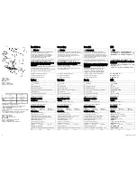
Bild 2: Aufbau
Figure 2: Design
Figura 2: Diseño
图
2:
结构
Figure 2: Structure
Figura 2: Configurazione
Рисунок
2:
Конструкция
*1)
Endanschlag nicht höher belasten
*1)
Do not subject the end stop to any higher stress
*1)
Carga máxima del tope de fin de carrera
*1)
末端止挡勿过高负载
*1)
Ne pas appliquer une contrainte plus élevée à la butée de
fin de course
*1)
Non caricare ulteriormente l'arresto di fine corsa
*1)
Не
превышать
нагрузку
на
концевой
упор
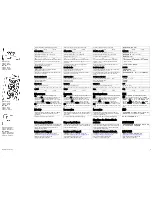
Bild 3: Klemmendaten
Figure 3: Terminal data
Figura 3: Datos de los bornes
图
3:
端子数据
Figure 3: Caractéristiques des bornes
Figura 3: Dati dei morsetti
Рисунок
3:
Информация по клеммам
Anschließen
WARNUNG
Vor Beginn der Installations- oder Instandhaltungs-
arbeiten ist der Hauptschalter der Anlage
auszuschalten und gegen Wiedereinschalten zu
sichern. Bei Nichtbeachtung kann das Berühren
spannungsführender Teile Tod oder schwere
Körperverletzung zur Folge haben.
Für die Installation der Geräte sind die einschlägigen
länderspezifischen Vorschriften zu beachten.
Wichtiger Hinweis: Eingangsseitig ist eine Sicherung
oder ein Leitungs- oder Motorschutzschalter
vorzusehen.
Für 6ES7307-1KA02-0AA0 verwenden sie Kupferdraht
zugelassen für 65/75 °C (nur bei UL508).
Der Anschluss der Versorgungsspannung muss gemäß
IEC 60364 und EN 50178 ausgeführt werden.
Siehe Bild 3 Klemmendaten (Seite 2)
Siehe Bild 4 Eingang (Seite 3)
Siehe Bild 5 Ausgang (Seite 3)
Aufbau
①
AC-Eingang
②
DC-Ausgang
③
Kontrollleuchte
④
ON / OFF Schalter
⑤
Schraube(n) zur Fixierung auf Profilschiene
⑥
Konvektion
⑦
Freiraum oberhalb/unterhalb
Siehe Bild 2 Aufbau (Seite 2)
Betriebsmodus
Signalisierung
LED grün: Ausgangsspannung > 21 V
Siehe Bild 6 Signalisierung (Seite 3)
Technische Daten
6ES7307-
1BA01-0AA0
6ES7307-
1EA01-0AA0
6ES7307-
1KA02-0AA0
Eingangsgrößen
Eingangsnennspannung U
e nenn
:
1 AC 120/230 V, 50 - 60 Hz
Spannungsbereich: AC 85 - 132/170 - 264 V
automatische Spannungsbereichsumschaltung
Netzfrequenzbereich: 47 - 63 Hz
Netzausfallüberbrückung:
> 20 ms (bei U
e nenn
: 93/187 V)
Eingangsnennstrom I
e nenn
:
0,9/0,5 A
2,3/1,2 A
4,2/1,9 A
Eingangssicherung: intern
Empfohlener Leitungsschutzschalter Charakteristik C:
3 A
6 A
10 A
Connecting
WARNING
Before starting any installation or maintenance work,
the main system switch must be opened and measures
taken to prevent it from being reclosed. If this
instruction is not observed, touching live parts can
result in death or serious injury.
For installation of the devices, the relevant country-
specific regulations must be observed.
Important note: A fuse, a miniature circuit breaker or
circuit breaker must be provided at the input.
For 6ES7307-1KA02-0AA0, use copper wire, approved
for 65/75 °C (only for UL508).
The supply voltage must be connected according to
IEC 60364 and EN 50178.
See Figure 3 Terminal data (Page 2)
See Figure 4 Input (Page 3)
See Figure 5 Output (Page 3)
Structure
①
AC input
②
DC output
③
Indicator light
④
ON / OFF switch
⑤
Screw(s) to fix to the mounting rail
⑥
Convection
⑦
Clearance above/below
See Figure 2 Design (Page 2)
Operating mode
Signaling
Green LED: Output voltage > 21 V
See Figure 6 Signaling (Page 3)
Technical data
6ES7307-
1BA01-0AA0
6ES7307-
1EA01-0AA0
6ES7307-
1KA02-0AA0
Input variables
Rated input voltage U
in rated
:
1 AC 120/230 V, 50 - 60 Hz
Rated operating voltage: AC 85 - 132/170 - 264 V
Automatic voltage range switchover
Line frequency range: 47 - 63 Hz
Power failure buffering:
> 20 ms (at U
in rated
: 93/187 V)
Rated input current I
in rated
:
0.9/0.5 A
2.3/1.2 A
4.2/1.9 A
Input fuse: Internal
Recommended miniature circuit breaker characteristic C:
3 A
6 A
10 A
Conexión
ADVERTENCIA
Antes de comenzar trabajos de instalación o
mantenimiento, se debe desconectar el interruptor
principal de la instalación y asegurarlo contra una
posible reconexión. Si no se observa esta medida, el
contacto con piezas bajo tensión puede provocar la
muerte o lesiones graves.
A la hora de instalar los aparatos, se tienen que
observar las disposiciones o normativas específicas de
cada país.
Nota importante: en el lado de entrada debe instalarse
un fusible o bien un automático magnetotérmico o un
guardamotor.
Para 6ES7307-1KA02-0AA0 utilice hilo de cobre
homologado para 65/75 °C (solo en UL508).
La conexión a la tensión de alimentación debe
realizarse conforme a IEC 60364 y EN 50178.
Ver Figura 3 Datos de los bornes (Página 2)
Ver Figura 4 Entrada (Página 3)
Ver Figura 5 Salida (Página 3)
Diseño
①
Entrada AC
②
Salida DC
③
Lámpara de control
④
Interruptor ON/OFF
⑤
Tornillos para la fijación en el perfil soporte
⑥
Convección
⑦
Espacio libre arriba/abajo
Ver Figura 2 Diseño (Página 2)
Modo de servicio
Señalización
LED verde: Tensión de salida > 21 V
Ver Figura 6 Señalización (Página 3)
Datos técnicos
6ES7307-
1BA01-0AA0
6ES7307-
1EA01-0AA0
6ES7307-
1KA02-0AA0
Magnitudes de entrada
Tensión nominal de entrada U
e nom
:
1 AC 120/230 V, 50 - 60 Hz
Rango de tensión: AC 85 - 132/170 - 264 V
Cambio automático de rango de tensión
Rango de frecuencia de red: 47 - 63 Hz
Puenteo de fallos de red:
> 20 ms (con U
e nom
: 93/187 V)
Intensidad nominal de entrada I
e nom
0,9/0,5 A
2,3/1,2 A
4,2/1,9 A
Fusible de entrada: interno
Automático magnetotérmico recomendado curva C:
3 A
6 A
10 A
接线
警告
开始安装或进行维护工作前应该断开装置的总开关,
防止设备重新合闸。违反该规定可能会导致作业人员接
触到带电零部件,从而导致严重的人身伤害甚至死亡。
设备安装同时需遵循本国相关的作业规范。
重要提示:设备输入侧必须配备熔断器、馈线断路器或
者电机断路器。
针对
6ES7307-1KA02-0AA0
使用适用于
65/75 °C
的同
芯线(仅限
UL508
)。
必须按照
IEC 60364
和
EN 50178
标准连接供电电压。
参见
图
3
端子数据
(
页
2)
参见
图
4
输入
(
页
3)
参见
图
5
输出
(
页
3)
结构
①
AC
输入
②
DC
输出端
③
LED
④
ON / OFF
开关
⑤
型材导轨固定螺钉
⑥
对流
⑦
上方
/
下方空间
参见
图
2
结构
(
页
2)
运行方式
信号指示
绿色
LED
:输出电压
> 21 V
参见
图
6
信号指示
(
页
3)
技术数据
6ES7307-
1BA01-0AA0
6ES7307-
1EA01-0AA0
6ES7307-
1KA02-0AA0
输入变量
额定输入电压
U
额定输入
:
单相
120/230 V AC
,
50 - 60 Hz
电压范围:
85 - 132/170 - 264 V AC
电压范围自动转换
电网频率范围:
47 - 63 Hz
断电缓冲:
> 20 ms
(在
U
额定输入
时
:93/187 V
)
额定输入电流
I
额定输入
:
0.9/0.5 A
2.3/1.2 A
4.2/1.9 A
输入点熔断器:内置
推荐的小型断路器(
C
特性):
3 A
6 A
10 A


