background image


2


Safety Guidelines 

This manual contains notices you have to observe in order to ensure your personal safety, as well as to prevent 

damage to property. The notices referring to your personal safety are highlighted in the manual by a safety alert 

symbol, notices referring only to property damage have no safety alert symbol. These notices shown below are 

graded according to the degree of danger. 

!


Danger 
indicates that death or severe personal injury will result if proper precautions are not taken. 

!


Warning 
indicates that death or severe personal injury may result if proper precautions are not taken. 

!


Caution 
with a safety alert symbol, indicates that minor personal injury can result if proper precautions are not taken. 


Caution 
without a safety alert symbol, indicates that property damage can result if proper precautions are not taken. 


Notice 
indicates that an unintended result or situation can occur if the corresponding information is not taken into 

account. 

If more than one degree of danger is present, the warning notice representing the highest degree of danger will 

be used. A notice warning of injury to persons with a safety alert symbol may also include a warning relating to 

property damage. 


Qualified Personnel 

The device/system may only be set up and used in conjunction with this documentation. Commissioning and 

operation of a device/system may only be performed by qualified personnel. Within the context of the safety notes 

in this documentation qualified persons are defined as persons who are authorized to commission, ground and 

label devices, systems and circuits in accordance with established safety practices and standards. 

Prescribed Usage 

Note the following: 

!


Warning 
This device may only be used for the applications described in the catalog or the technical description and only in 

connection with devices or components from other manufacturers which have been approved or recommended 

by Siemens. Correct, reliable operation of the product requires proper transport, storage, positioning and 

assembly as well as careful operation and maintenance. 

Trademarks 

All names identified by ® are registered trademarks of the Siemens AG. The remaining trademarks in this 

publication may be trademarks whose use by third parties for their own purposes could violate the rights of the 

owner. 

Disclaimer of Liability 

We have reviewed the contents of this publication to ensure consistency with the hardware and software 

described. Since variance cannot be precluded entirely, we cannot guarantee full consistency. However, the 

information in this publication is reviewed regularly and any necessary corrections are included in subsequent 

editions. 


Siemens AG 
Automation and Drives 
Postfach 48 48 
90437 NÜRNBERG 
DEUTSCHLAND 

Order No.: C79000-G8976-C211-02 
Release 06/2006 

Copyright © Siemens AG 2006 
Technical data subject to change 

Содержание SIMATIC NET SINAUT MD720-3

Страница 1: ...ual Preface Contents Introduction 1 Inserting the SIM card 2 Connecting the device and switching on the device 3 SINAUT MD720 3 in Terminal Mode 4 SINAUT MD720 3 in OPC Mode 5 Service function 6 Technical Data 7 Glossary C79000 G8976 C211 Release 06 2006 ...

Страница 2: ...sioning and operation of a device system may only be performed by qualified personnel Within the context of the safety notes in this documentation qualified persons are defined as persons who are authorized to commission ground and label devices systems and circuits in accordance with established safety practices and standards Prescribed Usage Note the following Warning This device may only be use...

Страница 3: ...unit to supply the SINAUT MD720 3 must comply with NEC Class 2 circuits as outlined in the National Electrical Code ANSI NFPA 70 only When connecting to a battery or accumulator make sure that an all pole circuit breaker main battery switch with sufficient selectivity and a fuse with sufficient selectivity e g Pudenz FKS Fuse 32V 3A Order No 162 6185 430 are provided between the device and the bat...

Страница 4: ...ameter Radio device Warning Never use the device in places where the operation of radio devices is prohibited The device contains a radio transmitter which could in certain circumstances impair the functionality of electronic medical devices such as hearing aids or pacemakers You can obtain advice from your physician or the manufacturer of such devices To prevent data carriers from being demagneti...

Страница 5: ...nd to comply with the limits for a Class A digital device pursuant to Part 15 of the FCC Rules These limits are designed to provide reasonable protection against harmful interference in a residential installation This equipment generates uses and can radiate radio frequency energy and if not installed and used in accordance with the instructions may cause harmful interference to radio communicatio...

Страница 6: ... or working at distances closer than those listed below ensure the transmitter has been disabled RF Exposure mobile Caution Typically the antenna connected to the transmitter is an omni directional antenna with 0dB gain Using this antenna the total composite power in PCS mode is smaller than 1 watt ERP The internal external antennas used for this mobile transmitter must provide a separation distan...

Страница 7: ...x 49 0 180 5050 223 You will find further information on our Technical Support on the Web at http www siemens com automation service Service Support on the Internet In addition to our documentation services you can also make use of all our knowledge on the Internet http www siemens com automation service support Here you will find Up to date product information Updates FAQs Frequently Asked Questi...

Страница 8: ...ATIC NET products In the catalog CA 01 In the catalog IK PI specifically for SIMATIC NET products SIMATIC training center To familiarize you with the systems and products we offer a range of courses Please contact your regional training center or the central training center in D 90327 Nuernberg Phone 49 911 895 3200 http www sitrain com SIMATIC NET training center For courses specifically on produ...

Страница 9: ...operation 25 4 5 Entering AT commands 26 4 6 Use AT commands 28 4 7 Supported AT commands in Terminal Mode 30 5 SINAUT MD720 3 in OPC Mode 57 5 1 OPC Mode activation 58 5 2 Operating requirements in OPC Mode GPRS subscriber contract 58 5 3 Functions of the LEDs in OPC Mode 59 5 4 PIN in OPC Mode 60 5 5 Log in to SINAUT MICRO SC 62 6 Service functions 63 6 1 Switching between Terminal mode and OPC ...

Страница 10: ...Contents SINAUT MD720 3 10 C79000 G8976 C211 ...

Страница 11: ... Mode refer to page 23 or page 58 forces a restart of the device Terminal mode The SINAUT MD720 3 establishes radio data connections via a GSM network Global System for Mobile Communication using modem connections via CSD Circuit Switched Data by sending SMS Short Message Service Notice You will find further information about the Terminal Mode and its use in combination with TIM devices of the SIN...

Страница 12: ...n OPC server SINAUT MICRO SC using SMS from a S7 200 device to any remote station which can receive SMS Therefore the SINAUT MD720 3 will be configured by program building blocks of the connected PLC The SINAUT MD720 3 establishes autonomous the radio data connection via GPRS between a S7 200 device and the OPC server SINAUT MICRO SC Notice You will find information about the OPC Mode in the syste...

Страница 13: ...f you use a lot of SIM cards it can be helpful to set all PINs to the same PIN number You can do this i e by using a mobile phone Please observe the security requirements of your organization To insert the SIM card proceed as follows 1 Make sure that the device is disconnected from the supply voltage 2 The SINAUT MD720 3 must be opened to insert the SIM card The housing is fastened by two clamps o...

Страница 14: ... a suitable object press one of the clamps cautiously see figure 2 2 so that the catch opens figure 2 2 4 Remove the rear section of the housing see figure 2 3 figure 2 3 5 The SIM card holder is visible on the motherboard see figure 2 4 figure 2 4 1 SIM card holder ...

Страница 15: ... cautiously about 2 mm to the left in the direction of the arrow see red arrow in figure 2 5 so that it can be raised figure 2 5 7 Raise the flap of the SIM card holder so that you can insert the SIM card see figure 2 6 figure 2 6 8 In figure 2 7 the compartment into which you can insert the SIM card is emphasized in white figure 2 7 ...

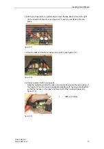
Страница 16: ...ip pointing down The flap has a groove for this purpose The notched corner of the SIM card has to point towards the front of the device see figure 2 8 figure 2 8 10 Slide the SIM card down into the flap as far as possible see figure 2 9 figure 2 9 11 Lower the flap paying attention to the notched corner of the SIM card see figure 2 10 figure 2 10 ...

Страница 17: ...into place figure 2 11 13 Now the SIM card holder is locked into position see figure 2 12 figure 2 12 14 Finally re attach both housing parts Slide the motherboard into the rails on top and bottom inside the rear section of the housing Close the housing by slightly pressing both housing parts together so that the clamps on the upper and lower part of the housing engage see figure 2 13 figure 2 13 ...

Страница 18: ...Inserting the SIM card SINAUT MD720 3 18 C79000 G8976 C211 15 The housing is locked when both clamps have clicked shut see figure 2 14 figure 2 14 ...

Страница 19: ... the upper part of the front Impedance approx 50 Ohm Caution Please use only antennas of the SINAUT MD720 3 accessory program Other antennas may disturb the product characteristics and may even cause defects 1 Connectors for supply voltage 24 V DC voltage nominal 2 Antenna 3 LEDs S Status Q Quality C Connect 4 X1 RS232 For connection of the application OR or the service PC ...

Страница 20: ...e used to indicate the device status The function of the LEDs is different in terminal and OPC Mode You will find the explanation of the function in Terminal Mode in chapter 4 3 Functions of the LEDs in Terminal Mode and in OPC Mode in chapter 5 3 Functions of the LEDs in OPC Mode Serial interface X1 For data transmission Connect the application e g machine vending machine sensor computer with the...

Отзывы: