background image


SIMATIC Box PC 827B 
Getting Started, 07/2008, A5E01127540-02 

7


Description 

2

2.1


External structure 


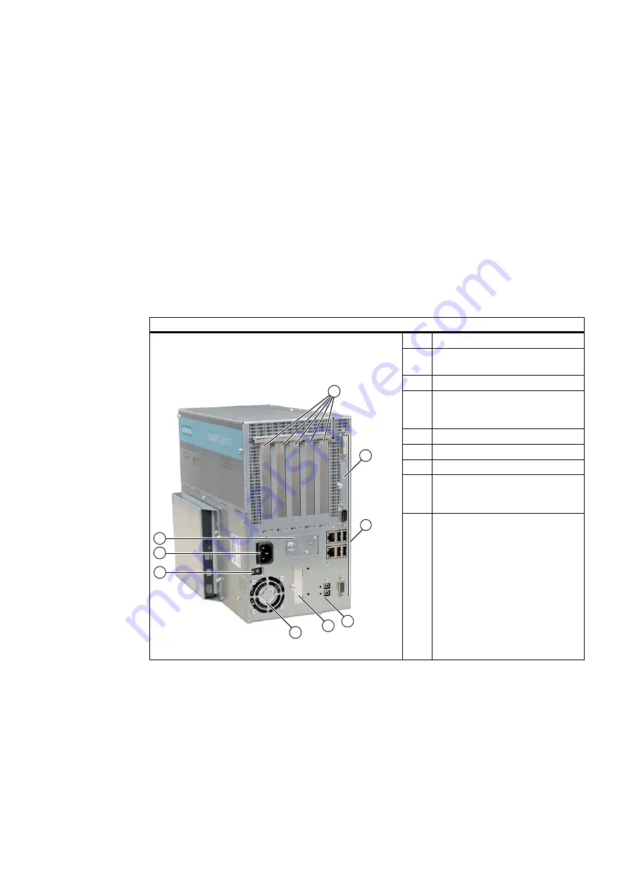
Front view 

(1) 

5 slots for expansion modules 

(2) 

Cover for Compact Flash Card 

slot 

(3) 

Front interfaces  

(4) 

Status display: Two part               

7 segment display and two LEDs 

for POST code (optional) 

(5) 

Slot for CompactFlash card 

(6) 

Power supply fan  

(7) 

On / Off switch 

(8) 

IEC connector for AC power 

supply or connection for 24 V DC 

power supply 


(9) 

Battery compartment 


Содержание SIMATIC Box PC 827B

Страница 1: ..._ ______________ ______________ ______________ ______________ ______________ Introduction 1 Description 2 Application Planning 3 Mounting 4 Connecting 5 Commissioning 6 Troubleshooting 7 Dimensional drawings 8 Appendix A SIMATIC Industrial PC SIMATIC Box PC 827B Getting Started 07 2008 A5E01127540 02 ...

Страница 2: ... documentation Commissioning and operation of a device system may only be performed by qualified personnel Within the context of the safety notes in this documentation qualified persons are defined as persons who are authorized to commission ground and label devices systems and circuits in accordance with established safety practices and standards Prescribed Usage Note the following WARNING This d...

Страница 3: ...nting 21 4 1 Installing the device 21 4 2 Installation of the device with mounting brackets 22 4 3 Installation of the device with the vertical mounting kit 23 5 Connecting 25 5 1 Connecting peripherals 25 5 2 Connecting the 120 V 230 V Ac power supply 26 5 3 Connecting the 24 V DC power supply 28 5 4 Connecting equipotential bonding 29 6 Commissioning 31 6 1 Requirements for commissioning 31 6 2 ...

Страница 4: ...Table of contents SIMATIC Box PC 827B 4 Getting Started 07 2008 A5E01127540 02 A Appendix 39 A 1 Guidelines and declarations 39 A 2 Certificates and approvals 41 A 3 Service and support 43 ...

Страница 5: ...ting instructions SIMATIC Box PC 827B The operating instructions are available on the supplied Documentation and Drivers CD To view and print the operating instructions run Start and follow the instructions on the screen The operating instructions provide useful information on many topics such as the hardware expansion options modification of the system configuration and technical data Conventions...

Страница 6: ...Introduction SIMATIC Box PC 827B 6 Getting Started 07 2008 A5E01127540 02 ...

Страница 7: ...s for expansion modules 2 Cover for Compact Flash Card slot 3 Front interfaces 4 Status display Two part 7 segment display and two LEDs for POST code optional 5 Slot for CompactFlash card 6 Power supply fan 7 On Off switch 8 IEC connector for AC power supply or connection for 24 V DC power supply 9 Battery compartment ...

Страница 8: ...008 A5E01127540 02 Rear view 1 Steel cover plate for the operator panel interfaces 2 Rating label with serial number 3 Device fan Side view drive side 1 Input data of the power supply 2 Drive bay module for hard disks and DVD burner Bottom 1 Connection for equipotential bonding ...

Страница 9: ...disconnect the device from mains When the switch is in position Off the device is still supplied with mains voltage in order to generated the internal auxiliary voltage for the power supply WARNING The On Off switch does not disconnect the device from the supply system NOTICE Close the operating system before shutting down the device with the on off switch otherwise data may be lost ...

Страница 10: ...Compact Flash card 3 COM Serial V 24 port 4 ETHERNET 2 RJ45 Ethernet connections for 10 100 1000 Mbps 5 USB 2 0 4 ports for USB devices only 2 ports can be simultaneously used as high current 6 PROFIBUS MPI MPI interface RS485 electrically isolated optional 9 pin D sub socket optional product model 7 PROFINET CP 1616 onboard interface three RJ45 connectors optional product characteristic The inter...

Страница 11: ...overs the interfaces described below 2 I O interface for connecting front panel components 3 USB 2 0 for front 4 LVDS display interface for TFT displays up to 1024 x 768 pixels 5 Access to 2nd LVDS display interface for TFT displays up to 1280 x 1024 AC power supply Position of the IEC power connector Description IEC power connector to AC power supply of the device The maximum permitted power rang...

Страница 12: ...on elements SIMATIC Box PC 827B 12 Getting Started 07 2008 A5E01127540 02 DC power supply Position of the DC power connector Description Plug connector for DC power supply of the device 1 2 3 24 V DC ground PE ground terminal ...

Страница 13: ...O device cannot be addressed IO controller Duplicate IP address Flashes rapidly Exception error diagnostics via Web or SNMP is no longer possible SF PROFINET optional Status display for CP 1616 onboard AN Diagnostics information available No communication established Virtual status displays The two virtual CP 1616 LEDs are only visible in the SIMATIC software and can be read via SNMP RUN CP is act...

Страница 14: ...segment displays with two dual color LEDs 1 2 x 7 segment display 2 LED H1 3 LED H2 7 segment display LED H1 LED H2 Power on status display test 88h Orange Orange BIOS self test xxh see BIOS postcode Off Off BIOS self test completed 00h Off Off Operating system is running or application driven 00h Off Off Operating system is shut down 88h Off Off ...

Страница 15: ...nsure that no moisture condensation develops on or inside the device If condensation has developed on the device wait at least 12 hours before you switch it on 3 2 Unpacking and checking the delivery unit Unpacking the device Note the following points when you unpack the unit It is advisable not to dispose of the original packing material Keep it in case you have to transport the unit again Please...

Страница 16: ...mber S VP is found on the rating plate Rating plate Order number of the device Ethernet addresses The Ethernet addresses of the device can be viewed in the BIOS Setup F2 under Main Hardware Options Ethernet Address Microsoft Windows Product Key on the Certificate of Authenticity COA The COA label is bonded to the device The Product Key is always required to reinstall the operating system COA label...

Страница 17: ...pply fulfils the requirements for fire protected enclosures according to EN 60950 1 Therefore it can be installed without any additional fire protective covering The device with DC power supply does not fulfill the requirements according to EN 60950 1 in the power supply unit area The device must therefore be installed in such a ways is part of an operating area with restricted access e g a locked...

Страница 18: ...18 Getting Started 07 2008 A5E01127540 02 3 5 Permitted mounting positions PC mounting positions according to UL60950 1 UL508 EN60950 1 CSA22 2 No 60950 1 An inclination of 20 is permitted for all approved mounting positions Position 1 preferred Position 2 Position 3 desktop ...

Страница 19: ...s position The CD drawer opens upward or downward which can lead to mechanical damages in the drawer mechanism NOTICE When using the device in the area of Industrial Control Equipment UL 508 ensure that the it is classified as Open Type A mandatory requirement for approval or operation according to UL 508 is therefore installation of the device in an enclosure certified for UL 508 NOTICE Mounting ...

Страница 20: ...Application Planning 3 5 Permitted mounting positions SIMATIC Box PC 827B 20 Getting Started 07 2008 A5E01127540 02 ...

Страница 21: ...r the system is necessary to avoid endangering persons With this especially the programming configuration and wiring of the inserted I O modules have to be executed in accordance with the necessary risk analysis identified safety performance SIL PL or Cat The intended use of the device has to be secured The correct use of the device has to be verified with a function test on the system This test c...

Страница 22: ...included M3 x 5 mm screws with a max insertion depth of 5 mm included in package Instructions for wall mounting Mounting examples Material Hole diameter Mounting Concrete 8 mm diameter 60 mm depth Dowel 8 mm 50 mm screws 4 mm 50 mm Plasterboard min 13 mm thick 14 mm diameter Tilting dowel diameter 4 mm min length 50 mm Metal min 2 mm thick 5 mm diameter Metal screws diameter 4 mm min length 15 mm ...

Страница 23: ...3 Installation of the device with the vertical mounting kit With the available optional vertical mounting kit you have the possibility to implement a place saving installation Mounting the vertical mounting plate onto the device 1 Remove the equipotential bonding screw 1 from the device and attach it with the vertical mounting plate 2 ...

Страница 24: ...e vertical mounting kit SIMATIC Box PC 827B 24 Getting Started 07 2008 A5E01127540 02 2 Attach the vertical mounting plate with four M4 screws and three M3 screws to the device Note Following instructions in the Permitted mounting positions section ...

Страница 25: ... CAUTION Strictly adhere to the specifications in the manuals for the peripheral devices NOTICE The connected or built in peripherals should not introduce a counter emf into the device A counter emf greater than 0 5 V to ground on the 3 3 VDC 5 VDC 12 VDC power rail due to a connected or integrated component can prevent normal operation or even destroy the computer When measuring the counter emf r...

Страница 26: ...onform with local mains voltage CAUTION The mains connector must be disconnected to fully isolate the device from mains Ensure easy access to this area A master mains disconnect switch must be installed if the device is mounted in a switch cabinet Always ensure free and easy access to the power inlet on the device or that the safety power outlet of the building installation is freely accessible an...

Страница 27: ...e connector must be compliant with NEMA 5 15 120 V AC power supply To be used is a flexible power cord approved to UL and with CSA label and which has the following features Type SJT with three leads min 18 AWG conductor cross section max 4 5 m in length and parallel ground contact connector 15 A min 125 V 240 VAC power supply Use a flexible power cord which is approved to UL and CSA and which has...

Страница 28: ...rrent of the 24 V DC power source so that a short circuit will not damage the cable Only connect cables with a minimum cross section of 1 3 mm2 AWG16 and a maximum cross section of 3 3 mm2 AWG12 NOTICE The 24 V DC power source must be adapted to the input data of the device see specifications Connecting Steps for connecting the device to the 24 V DC power supply 1 Ensure that the ON OFF switch is ...

Страница 29: ...tem in which the device is to be installed The minimum cross section is 5 mm2 The equipotential bonding terminal ensures that interference signals generated by external power supply cables signal cables or cables to the I O modules are safely discharged to earth Connecting equipotential bonding Connect the equipotential bonding terminal on the device large surface large area contact to the central...

Страница 30: ...Connecting 5 4 Connecting equipotential bonding SIMATIC Box PC 827B 30 Getting Started 07 2008 A5E01127540 02 ...

Страница 31: ... hours before you switch it on 6 2 Basic commissioning initial startup The PC operating system is automatically set up the first time you switch on the device Procedure 1 Set the ON Off switch to I position On The PC performs a POST During the self test this message appears Press F2 to enter SETUP or ESC to show the Boot menu 2 Wait until this message is cleared then follow the instructions on the...

Страница 32: ... the operating system with Windows XP Embedded is automatically opened when the startup routine is completed 6 3 Reinstalling the software 6 3 1 General installation procedure In case of software errors you can reinstall your software using the Recovery CD the Documentation and Drivers CD or the Restore DVD Recovery CD Contains the tools for setting up hard disk drives and the operating system Doc...

Страница 33: ...n power save mode Press any key on the keyboard The brightness button has been set to dark Increase the screen brightness For detailed information refer to the monitor operating instructions Check whether the power cord has been properly connected to the monitor and to the system unit or to the grounded shockproof outlet Check whether the monitor cable has been properly connected to the system uni...

Страница 34: ... 2 0 device connected but USB 2 0 is disabled Enable USB 2 0 USB device not responding Operating system does not support the USB port Enable USB Legacy Support for the mouse and keyboard For other devices you need the USB drivers for the respective operating system DVD The front loader does not open The device is switched off or the open close button is disabled by a software application Emergency...

Страница 35: ...SIMATIC Box PC 827B Getting Started 07 2008 A5E01127540 02 35 Dimensional drawings 8 8 1 Dimensional Drawing of the Device 2SWLFDO GULYH Figure 8 1 Dimensional drawing for mounting with angle bracket ...

Страница 36: ...he Device SIMATIC Box PC 827B 36 Getting Started 07 2008 A5E01127540 02 2SWLFDO GULYH Figure 8 2 Dimensional drawing for mounting without angle bracket NOTICE When mounting devices with optical drives or WinAC backup batteries change the fitting depth ...

Страница 37: ...ngs 8 1 Dimensional Drawing of the Device SIMATIC Box PC 827B Getting Started 07 2008 A5E01127540 02 37 9 9 Figure 8 3 Dimensional drawings for vertical mounting model without DVD burner and without WinAC backup battery ...

Страница 38: ...al drawings 8 1 Dimensional Drawing of the Device SIMATIC Box PC 827B 38 Getting Started 07 2008 A5E01127540 02 NOTICE When mounting devices with optical drives or WinAC backup batteries change the fitting depth ...

Страница 39: ...07 EN 61000 6 2 2005 The device is also compliant with EN 61000 3 2 2006 harmonic currents and EN 61000 3 3 1995 A1 2001 A2 2005 voltage fluctuation and flicker Low voltage directive The devices with AC and DC power supply are compliant with the requirements of the EC Directive 2006 95 EEC Low Voltage Directive Conformance with this directive has been verified according to EN60950 1 2001 A11 2004 ...

Страница 40: ...ng Started 07 2008 A5E01127540 02 Connecting peripherals Noise immunity requirements to EN 61000 6 2 are met if connected peripherals are suitable for industrial applications Peripheral devices are only be connected via shielded cables ...

Страница 41: ...ts for a Class A digital device pursuant to Part 15 of the FCC Rules These limits are designed to provide reasonable protection against harmful interference when the equipment is operated in a commercial environment This equipment generates uses and can radiate radio frequency energy and if not installed and used in accordance with the instruction manual may cause harmful interference to radio com...

Страница 42: ...1127540 02 CANADA Canadian Notice This Class A digital apparatus complies with Canadian ICES 003 Avis Canadian Cet appareil numérique de la classe B est conforme à la norme NMB 003 du Canada AUSTRALIA This product meets the requirements of the AS NZS CISPR22 ...

Страница 43: ...com sitrain Find a contact at Phone 49 911 895 3200 Technical support Tel 49 180 5050 222 Fax 49 180 5050 223 http www siemens com automation service You will find support request web form at http www siemens de automation support request When you contact the customer support please have the following information for the technician on hand BIOS version Order No MLFB of the device Installed additio...

Страница 44: ...Index SIMATIC Box PC 827B 44 Getting Started 07 2008 A5E01127540 02 ...

Отзывы: