Appendices
A.1 Structure of user data/process data
ATD4xxW Door Controller for Industrial Applications
System Manual, 01/2017, A5E38080677-AB
293
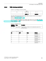
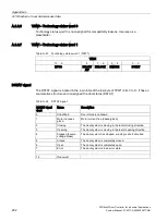
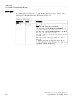
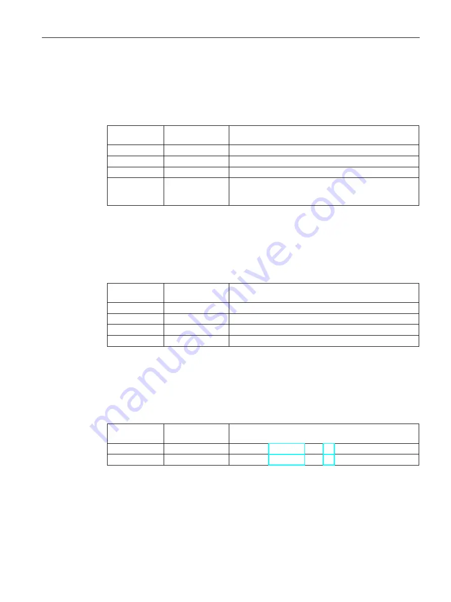
DMODE signal
The DMODE signal is located in the low byte of TZW1 (bits 4 to 5). It has an enumerative
structure and is assigned the door mode (DMODE) .
Table A- 25 DMODE signal
DMODE signal
value
Name
Description
0
Normal mode
Both end positions determined after power on, ready to run
1
Initial mode
Both end positions must be determined after power on
2
Learn run mode
Both end positions and other door properties are determined
3
Special mode
The system is in an error state or special mode (system is
shutting down, powering up or saving safety-related parame-
ters)
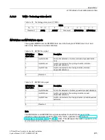
DBLOCK signal
The DBLOCK signal is located in the low byte of TZW1 (bits 6 to 7). It has an enumerative
structure and is assigned the obstruction detection (DBLOCK).
Table A- 26 DBLOCK signal
DBLOCK signal
value
Name
Description
0
None
There is no obstruction
1
In opening direction An obstruction was detected in the opening direction
2
In closing direction An obstruction was detected in the closing direction
3
Reserved
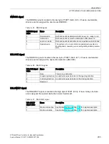
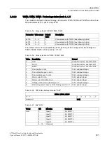
DBLCWAIT signal
The DBLCWAIT signal is located in the high byte of TZW1 (bit 9). It has a binary structure
and is assigned the special obstruction mode "wait mode".
Table A- 27 DBLCWAIT signal
DBLCWAIT
signal value
Name
Description
0
Wait mode inactive See Section Wait mode (Page 74) for a signal description
1
Wait mode active
See Section Wait mode (Page 74) for a signal description

