Chapter 2
Installing the Device
RUGGEDCOM RX1100P
Installation Guide
10
Connecting DC Power
4
2
1
3
4
6
5
7
4
6
4
3
6
5
7
4
6
5
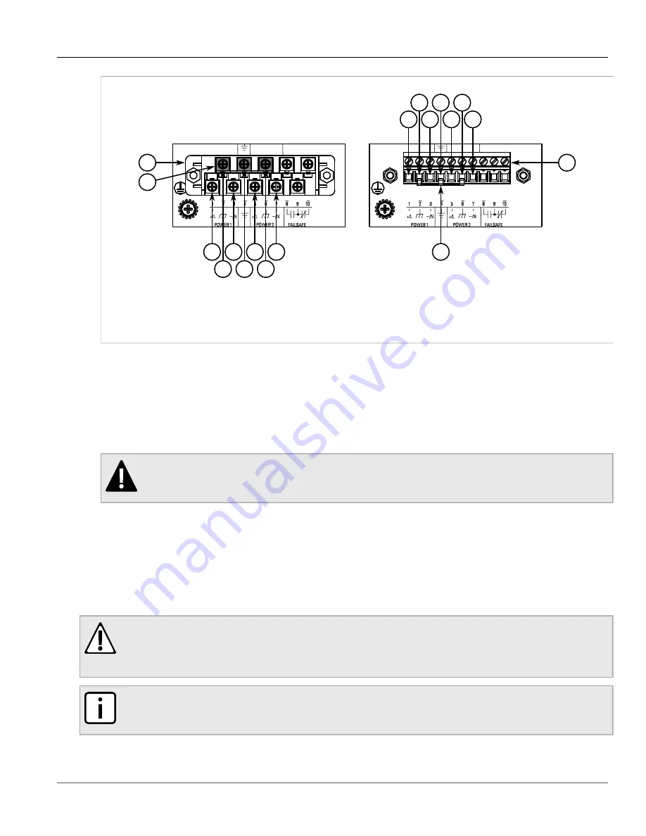
Figure 5: Terminal Block Wiring
1.
Screw-Type Terminal Block
2.
Pluggable Terminal Block
3.
Jumper
4.
Positive/Live (+/L) Terminal
5.
Negative/Neutral (-/N)
Terminal
6.
Surge Ground Terminal
7.
Chassis Ground Terminal
4. Connect the negative wire from the power source to the negative/neutral (-/N) terminal on the terminal block.
For more information, refer to
Section 2.2.3, “Wiring Examples”
.
5. Install the supplied metal jumper between terminals 2, 4 and 6 to connect the surge ground terminals to the
chassis ground terminal. The surge ground terminals are used as the ground conductor for all surge and
transient suppression circuitry internal to the unit.
6. Connect the ground terminal on the power source to the chassis ground terminal on the device. For more
Section 2.4, “Grounding the Device”
DANGER!
Electrocution hazard – risk of death, serious personal injury and/or damage to the device. Make
sure the supplied terminal block cover is always installed before the device is powered.
7. Install the terminal block cover.
Section 2.2.2
Connecting DC Power
To connect a high or low DC power supply to the device, do the following:
CAUTION!
Electrical hazard – risk of damage to equipment. Before testing the dielectric strength (HIPOT) in the
field, remove the metal jumper. This metal jumper connects transient suppression circuitry to chassis
ground and must be removed in order to avoid damage to transient suppression circuitry during testing.
NOTE
The terminal block is divided into separate terminals for each internal power supply. Make sure to
connect the external power supply to the appropriate terminals.
Содержание RUGGEDCOM RX1100P
Страница 10: ...RUGGEDCOM RX1100P Installation Guide Chapter 1 Introduction Ports Controls and Indicator LEDs 4 ...
Страница 38: ...RUGGEDCOM RX1100P Installation Guide Chapter 3 Communication Ports Connecting Multiple RS485 Devices 32 ...
Страница 46: ...RUGGEDCOM RX1100P Installation Guide Chapter 5 Dimension Drawings 40 ...


