background image

41 / 68

Siemens

RDU341   Basic Documentation

CE1P3172en

Building Technologies

2015-06-08

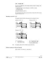
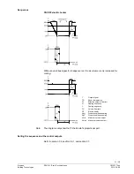
3.10.9  Electric heater interlock by supply air controller

(LTE mode only)

To avoid overheating of an electric heater, sufficient flow of supply air must be
guaranteed. The thermostat features the function “Interlock of el. heater via supply
air controller”, which is active when a supply air controller (e.g. Synco RMU7xx) is
used in the system. The supply fan controller sends the fan status (StatusSATC) to
the thermostat when the supply fan is running, after which the el heater is allowed
to turn on if there is a call for heat.
When the supply fan is not running, then the el. heater keeps turned off, even
though there is a demand for heat.
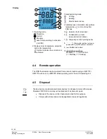
The fan symbol

 is displayed, when the supply fan is on.

·

  Electric heater enable via local input X1 / X2 or via KNX will override any release

by this interlock function and vise versa (last intervention wins).

·

  After power-up of the thermostat the electric heater is completely disabled for at

least 5 minutes or until a supply air controller is detected. If no supply fan
controller is in the system, the el. heater is allowed to turn on if there is a
demand for heat.

·

  The fan information is broadcast every 15 minutes or on change of value. If no

value is received any more, the thermostat will disable the interlock function after
a timeout of 31 minutes.

General rule: In case of insufficient air flow, the thermostat cannot protect the
electric heater against overtemperature. Therefore the electric heater MUST
feature a separate safety device (thermal cutout).

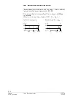
3.10.10 Primary fan overrun after switching off the electric

heater

To avoid overheating of an electric heater after it has been switched off, the air flow
must be maintained for a while.

In conjunction with a supply air controller (e.g. Synco RMU7xx) this will be
automatically assured by exchanging the necessary information. The supply fan
controller will only switch off the supply fan once all el. heaters are cooled off.

Note: The cool off time of the el. heater can be adjusted for each el. heater via
parameter "fan overrun time" (P54, factory setting 60sec).

General rule: In case of insufficient air flow, the thermostat cannot protect the
electric heater against overtemperature. Therefore the electric heater MUST
feature a separate safety device (thermal cutout).

Notes

Caution

Caution

Содержание RDU341

Страница 1: ...s Semi flush mount room thermostats with KNX communications RDU341 Basic Documentation Edition 1 1 CE1P3172en 2015 06 08 Building Technologies ...

Страница 2: ...perature setpoints 19 3 3 1 Description 19 3 3 2 Setting and adjusting setpoints 20 3 4 Applications overview 22 3 5 Additional functions 23 3 6 Control sequences 25 3 6 1 Sequences overview setting via parameter P01 25 3 6 2 Application mode 26 3 6 3 Minimum and maximum air volume 28 3 6 4 Single duct 29 3 6 5 Single duct with electric heater 30 3 6 6 Setpoints and sequences 32 3 7 Control output...

Страница 3: ...47 3 12 2 Parameter setting download via tool 48 3 12 3 Parameters of the Service level 49 3 12 4 Parameters of the Expert level with diagnostics and test 50 4 Handling 52 4 1 Mounting and installation 52 4 2 Commissioning 53 4 3 Operation 55 4 4 Remote operation 56 4 5 Disposal 56 5 Supported KNX tools 57 5 1 ETS 57 5 1 1 Parameter settings in ETS 57 5 2 ACS tool 57 5 2 1 Parameter settings in AC...

Страница 4: ...KNX see www siemens com synco 5 CE1N3127 KNX bus Data Sheet 6 CE1P3127 Communication via the KNX bus for Synco 700 900 and RXB RXL Basic Documentation 7 XLS template in HIT Planning and commissioning protocol communication Synco 700 8 CE1N3121 RMB395 central control unit Data Sheet 9 CE1Y3110 KNX S mode data points 10 Product data for ETS 11 CE1J3110 ETS product data compatibility list 12 0 92168e...

Страница 5: ...sses of the Siemens Regional Companies are available at www buildingtechnologies siemens com 1 3 3 Document use request to the reader Before using our products it is important that you read the documents supplied with or ordered at the same time as the products equipment applications tools etc carefully and in full We assume that persons using our products and documents are authorized and trained ...

Страница 6: ...sary The inputs outputs and parameters of an application can be influenced in various ways These are identified by the following symbols in this document Parameters identified by this symbol are set using ETS Parameters identified by this symbol are set using the ACS tool Setting RDU KNX parameters is only supported by the following tool versions ETS3f or higher ACS700 version 5 11 or higher Input...

Страница 7: ...r and AC 230V electric heater ON OFF Automatic or manual heating cooling changeover Backlit display AC 24 V operating voltage Room temperature control via built in temperature sensor or external room temperature return air temperature sensor Changeover between heating and cooling mode automatic via local sensor or bus or manually Selection of applications via DIP switches or commissioning tool ACS...

Страница 8: ...Remote operation and monitoring with web browser using the OZW772 or OZW775 web server Maximum energy efficiency due to exchange of relevant energy information e g with Synco 700 controllers e g heating demand cooling demand Alarming e g external fault contact condensation etc Monitoring input for temperature sensor or switch Engineering and commissioning can be done using local DIP switches HMI S...

Страница 9: ...ering and Service tool OCI700 OCI702 Interface for ACS RXB RXL Room controllers QAX Room unit for RXB RXL room controllers The RDU KNX devices can be integrated into the Siemens building automation and control systems BACS DESIGO Apogee or into 3rd party systems For integration either S mode group addressing or individual addressing can be used The workflow for integration into DESIGO Apogee is th...

Страница 10: ...l actuator DC 0 10 V for 2 and 3 port valves V P45 SSC61 4895 Electrical actuator DC 0 10 V for small valve 2 5 mm SSP61 4864 Electrical actuator DC 0 10 V for small valves 5 5 mm SSB61 4891 Electrical actuator DC 0 10 V for Combi valve VPI45 SSD61 4861 Electromotoric actuator DC 0 10V for valves 5 5 mm SQS65 4573 Thermal actuator DC 0 10 V for small valves and radiator valves STS61 4880 DC 0 10 V...

Страница 11: ...kage ARG86 3 N3009 Plastic mounting bracket for RDU semi flush mount thermostats for increasing the headroom in the conduit box by 10 mm ARG70 3 N3009 Conduit box for semi flush mounted thermostat ARG71 S55770 T137 N3009 KNX power supply 160 mA Siemens BT LV 5WG1 125 1AB01 KNX power supply 320 mA Siemens BT LV 5WG1 125 1AB11 KNX power supply 640 mA Siemens BT LV 5WG1 125 1AB21 ...

Страница 12: ...ternal or external sensor is also available as information on the bus With automatic changeover or continuous heating cooling symbols indicate that the system currently heats or cools heating or cooling output is activated With manual changeover P01 2 symbols indicate that the system currently operates in heating or cooling mode Thus the symbols are displayed even when the thermostat operates in t...

Страница 13: ...switches to Economy mode when the operating mode button is pressed only possible if parameter P02 is set to 2 Economy is sent via bus an operating mode switchover contact e g keycard contact presence detector window contact is active The contact can be connected to multifunctional input X1 X2 Set parameter P38 P40 to 3 P02 is irrelevant Window state is sent via bus e g from a KNX switch or a KNX p...

Страница 14: ...est priority you can always command an operating mode independent of all other settings or intervention via bus and local input Protection mode via bus from time schedule Protection mode sent by a time schedule has priority 2 It cannot be overridden by the user nor by an operating mode switchover contact Operating mode switchover contact If the contact is closed the operating mode changes to Econo...

Страница 15: ... user profile can be defined via parameter P02 factory setting is P02 1 P02 Without time schedule With time sche dule via bus Description 1 à à Switching manually between 2 modes Economy is not available factory setting Suited for hotel guest rooms or commercial buildings If a time schedule via bus is available then the Comfort mode can be temporarily extended see below 2 à à à à à Switching manua...

Страница 16: ... mode button again to stop the timer The following conditions must be fulfilled Mode selection via operating mode button is set to Protection Auto P02 1 and parameter P68 extend Comfort period is greater than 0 The time schedule via bus is Economy or Operating mode switchover is active During the temporary Comfort mode extension symbol appears If parameter P68 extend Comfort period 0 extended Comf...

Страница 17: ...06 00 Lunch break from 12 00 to 13 00 Precomfort The substitution parameter P88 for Precomfort via bus is set on the thermostats as follows Room 1 Comfort 1 Room 2 Economy 0 Operating mode switchover In room 1 the window is opened briefly once in the morning once in late afternoon and once at night 1 Only the opening in the morning has a direct impact on the effective room operating mode During lu...

Страница 18: ...the operating mode to Comfort temporary Comfort extension by pressing the operating mode button 2 At 13 00 the timer is reset due to mode change of the central time schedule In the afternoon the user switches the thermostat off by pressing the operating mode button 3 At 17 00 the user setting is reset to Economy by the time schedule At 19 30 the user again extends the Comfort mode 4 At 20 00 the t...

Страница 19: ...r heating or cooling applications e g single duct The setting range in cooling mode is from P09 40 C in place of 5 40 C The setting range in heating mode is from 5 P10 C in place of 5 40 C For heating and cooling applications e g single duct with el heater P09 is the setpoint for cooling and P10 the setpoint for heating The setpoint can no longer be adjusted via the rotary knob Examples Single duc...

Страница 20: ... EEPROM of thermostat Commissioning HMI Tool download Input LTE mode Input S mode Comfort basic setpoint Dead zone Comfort 1 Setpoints Heating Setpoints Cooling Comfort basic setpoint P08 Comfort basic setpoint P33 Dead zone Comfort 1 Setpoint Economy Heating Setpoint Economy Cooling Setpoints Heating Setpoints Cooling P11 Economy Heating P12 Economy Cooling Setpoint Protection Heating Setpoint Pr...

Страница 21: ... the basic setpoint Central setpoint shift is used for summer winter compensation in particular Setpoint shift does not affect the setpoints stored in parameters P08 P11 P12 P33 Local shift and central shift are added together Applies only to Comfort and Economy setpoints Protection setpoints are not shifted centrally The resulting current setpoint heating and cooling is limited by the Protection ...

Страница 22: ... ACS as well The tool offers the applications printed in bold text basic applications Application and output signal Diagram DIP switches Remote configuration via commissioning tool factory setting Synco ACS ETS 1 ON 2 3 Single duct Single duct heating or cooling DC 0 10 V output signal normal 3192S07 B1 T M V M V YV 1 ON 2 3 Single duct heating or cooling DC 10 0 V output signal inverted 1 ON 2 3 ...

Страница 23: ... connected to X1 X2 and parameter P38 P40 is 2 the water or supply air temperature acquired by the sensor is used to change over from heating to cooling mode or vice versa When the water air temperature is above 28 C parameter P37 the thermostat changes over to heating mode and to cooling mode when below 16 C parameter P36 If the water air temperature is between the 2 changeover points immediately...

Страница 24: ...iated damage to the building A dew point sensor with a potential free contact is connected to multifunctional input X1 or X2 If there is condensation the cooling valve is fully closed until no more condensation is detected and the cooling output is disabled temporarily The condensation symbol is displayed during temporary override and the fault Condensation in room will be sent via bus The input m...

Страница 25: ...air sequence can be done via supply air temperature sent by the primary controller The available sequences depend on the application Parameter P01 0 P01 1 P01 2 P01 3 Sequence c o signal on X1 X2 D1 c o signal via bus Supply air temp via bus Available for basic application ê Heating Cooling Manually select heating or cooling sequence Automatic heating cooling changeover Single duct ü ü ü ü ü 1 ü 1...

Страница 26: ...ol outside air if necessary The thermostat will open the damper and does not heat cool with the coils or the electric heater Function will be terminated by any operation on the thermostat Open damper fully if night purge condition is valid 1 5 Pre cool If Pre cool is received the room should be cooled down as fast as possible if necessary The thermostat will only allow cooling Cooling only 6 Off T...

Страница 27: ... Cool 3 5 Heating Cooling Cooling Cooling Night purge 4 Fan only 9 Heating Heating Cooling Cooling With applications Single duct with electric heater radiator heating cooling coil the control sequence state depends on the application mode and on the heating cooling demand Application Mode via bus Heating cooling demand Control sequence state Auto 0 Heating Heating No demand Heating cooling dependi...

Страница 28: ...ry setting for minimum and maximum air volume is 0 100 respectively These values can be changed using parameters P63 P64 If Vmin is greater than 0 a minimum air flow of Vmin is assured in Comfort and Economy mode In Protection or Economy mode with setpoint OFF Vmin is fixed to 0 Comfort or Economy mode Protection mode Vmin always 0 ...

Страница 29: ...ted to a minimum and maximum value if required see section 3 5 Modulating control DC 0 10 V The diagrams below show the control sequence for modulating PI control Heating only P01 0 Cooling only P01 1 Changeover P01 2 3 T C Room temperature XpH Proportional band Heating w Room temperature setpoint XpC Proportional band Cooling Y Control command Actuator Vmin Min limitation for output Vmax Max limi...

Страница 30: ... receives an ON command when the acquired room temperature drops below setpoint setpoint for electric heater Remote enabling disabling of the electric heater is possible via input X1 or X2 for tariff regulations energy savings etc Input X1 or X2 must be commissioned accordingly parameters P38 P40 See section 3 8 The electric heater can also be enabled disabled via bus If Enable electric heater inp...

Страница 31: ...utput signal TR Room temperature W Effective setpoint Comfort H Heating sequence C Cooling sequence YV Volume flow rate YE Electric heater XpH Proportional band heating XpC Proportional band cooling Vmin Minimum volume output Vmax Maximum volume output The diagrams only show the PI thermostat s proportional part Setting the sequence and the control outputs Refer to section 3 4 section 3 6 1 and se...

Страница 32: ...oints heating and above the Comfort setpoints cooling They can be set via parameters P11 P12 Economy mode and P65 P66 Protection mode Comfort mode Economy Protection mode Application Heating Cooling Heating Cooling Single duct Heating and Cooling Heating and Cooling Single duct with el heate W setpoint in Comfort mode WHeatEco Prot setpoint heating in Economy or Protection mode WCoolEco Prot setpo...

Страница 33: ... for the electric heater is output 1 When the acquired room temperature is above the setpoint electric heater 2 When the electric heater has been switched on for more than 1 minute A safety thermostat to prevent overheating must be provided externally 3 7 2 Control outputs configuration setting via DIP switches or tool Use DIP switch 3 on the inner side of the front panel to commission the signal ...

Страница 34: ...can also be connected rather than a sensor switch closed cooling see section 3 5 With single duct applications the input changes over the air sequence Heating cooling changeover is also possible via bus In this case the function must not be assigned to any local input X1 X2 D1 See also section 3 5 Diagnostic value 0 C is displayed for closed contact 100 C for open contact if a switch is connected ...

Страница 35: ... represent a visual signal DI KNX R X1 X2 Digital 7 Monitor input Digital Digital input to monitor the state of an external switch via bus DI KNX R X1 X2 Temp 8 Monitor input Temperature Sensor input to monitor the state of an external sensor e g QAH11 1 via bus AI Operational action can be changed between normally open NO and normally closed NC via parameter P39 P41 Each input X1 X2 must be confi...

Страница 36: ...ring via group addresses LTE mode Logical Tag Extended mode for easy engineering is used in conjunction with Synco 3 10 1 S mode This mode corresponds to KNX communications Connections are established via ETS by assigning communication objects to group addresses 3 10 2 LTE mode LTE mode was specifically designed to simplify engineering Unlike with S mode there is no need to create the individual c...

Страница 37: ... Synco Application Manual 12 To engineer and commission a specific system use the Synco700 planning and commissioning protocol XLS table in HIT 7 3 10 3 Zone addressing in LTE mode in conjunction with Synco In cases where RDU KNX room thermostats are used in LTE mode e g in conjunction with Synco zone addresses need to be allocated The following zone address must be defined together with the Synco...

Страница 38: ...eived from the same zone the thermostat will use the information received from the same apartment but with room 1 A 1 1 Office Example Commercial building In a commercial building the time switch information is sent by the RMB975 central control unit The zones are divided in so called Room groups e g 1 4 where each Room group can have an individual schedule A room thermostat in the same Room group...

Страница 39: ... A VAV box room B Fan coil room C DHW heating Heat demand Heat demand Heat demand Heat demand Heat requistion Heat distr zone source side 1 Heat distr zone 2 Heat distr zone 2 Heat distr zone 2 Heat distr zone 2 Setting values M V M V T T T In the case of a typical application the individual RDU RDG room thermostats when used with the RMB975 central control unit signal their heat demand directly t...

Страница 40: ...will no longer be periodically sent and will therefore reduce bus load 3 10 6 Startup The application is restarted after every reset so that all the connected motorized valve actuators are synchronized see section 3 7 After a reset it takes up to 5 minutes for all the connected room thermostats to restart This is designed to avoid overloading the network when restarting At the same time it reduces...

Страница 41: ...pply fan controller is in the system the el heater is allowed to turn on if there is a demand for heat The fan information is broadcast every 15 minutes or on change of value If no value is received any more the thermostat will disable the interlock function after a timeout of 31 minutes General rule In case of insufficient air flow the thermostat cannot protect the electric heater against overtem...

Страница 42: ...bus Prio Fault Display Error code Default fault text Text adjustable No fault 0 No fault ü 1 Bus power supply bus 5000 No bus power supply 2 Device address error Addr 6001 1 id device address 3 Condensation 4930 Condensation in the room ü 4 External fault input X1 AL1 9001 Fault input 1 ü 5 External fault input X2 AL2 9002 Fault input 2 ü Default alarm texts are stored in the thermostat s non vola...

Страница 43: ...nt value Damper 0 Normal Normal operation 1 EmergPressure Fully open 2 EmergDepressure Fully closed 3 EmergPurge Fully open 4 EmergShutdown Fully closed 5 EmergFire Fully closed Emergency signals have highest priority and command the control output accordingly Any ongoing function like fan overrun etc will be stopped immediately The priority is as follows 1 Smoke Emergency 1 4 2 Fire Emergency 5 3...

Страница 44: ...21 13 15 34 20 Room operating mode Window state 32 33 X1 temperature digital 35 20 22 Room temperature Comfort basic setpoint 34 35 X2 temperature digital 35 20 23 Room temperature Comfort setpoint 25 Control output VAV 40 26 31 Application mode 26 Heating output primary 2 40 34 20 Enable electric heater 23 34 30 Supply air temperature 42 6 Fault transmission 5 Fault state 24 42 4 Fault informatio...

Страница 45: ...onomy Protection 20 102 1 Byte CRT Effective room operating mode used by the thermostat considering time switch user selection window contact etc This state information is available via one 8 bit enumeration or three 1 bit communication objects 17 19 Note The thermostat does not support Precomfort 17 18 19 Room operating mode State Comfort State Economy State Protection ON OFF 1 002 1 bit CT Corre...

Страница 46: ...multifunctional input X1 D1 parameter P38 P42 Only one input source must be used either local input X1 X2 D1or KNX bus 31 Application mode HVAC control mode 20 105 8 bit CWU 0 Auto default Heating and or cooling 1 Heat Heating only 2 Morning warmup Heating only 3 Cool Cooling only 4 Night purge Open damper fully 5 Precool Cooling only 6 OFF Neither heating nor cooling 8 Emergency heat Heating only...

Страница 47: ... buttons and simultaneously for 3 seconds Release and press button again for 3 seconds within 2 seconds The display shows P01 Continue with step 2 1 Press buttons and simultaneously for 3 seconds Release and press button again for 3 seconds within 2 seconds The display shows P01 and service 2 Repeatedly press the or button to select the required parameter P01 P02 P08 P14 3171z99 End P13 3 Press an...

Страница 48: ...l operation using the OZW772 web server or the RMZ792 B bus operator unit Only the parameters for device address can be downloaded via ETS3 Professional This is to simplify and avoid a conflict It allows you to further engineer communication objects of an RDU previously commissioned vial local HMI or ACS assigning communication objects to group addresses The basic application can only be changed v...

Страница 49: ...alue correction 0 K 3 3 K P06 Standard display 0 0 Room temperature 1 Setpoint P07 Additional display information 0 0 No display 1 C and F 2 Outside temperature via bus 3 Time of day 12h via bus 4 Time of day 24h via bus P08 Comfort basic setpoint 21 C 5 40 C P09 Comfort setpoint minimum 5 C 5 40 C P10 Comfort setpoint maximum 35 C 5 40 C P11 Economy heating setpoint 15 C OFF 5 WCoolEco WCoolEco 4...

Страница 50: ...y air sensor AI 10 Presence detector DI P39 Normal position input X1 0 N O 0 Normally open Open 1 Normally closed Close P40 Input X2 1 Ext sensor 0 no function 1 Room temp ext sensor Return air temp AI 2 H C changeover AI DI 3 Operating mode contact DI 4 Dew point sensor DI 5 Enable electric heater DI 6 Fault input DI 7 Monitor input Digital 8 Monitor input Temp 9 Supply air sensor AI 10 Presence ...

Страница 51: ...tory setting for Area 0 Line 2 Can be changed by special management service e g from line coupler or via ACS commissioning tool 2 Type geographical zone A R S In RDG RDU sub zone fixed value 1 Parameter Name Range Diagnostics test d01 Application number NONE No application Sd Single duct SdEL Single duct with electric heater d02 X1 state 0 Not activated for DI 1 Activated DI 0 49 C Current temp va...

Страница 52: ...egulations to wire protect and earth the controller Warning No internal line protection for supply lines to external consumers Y10 Y21 Risk of fire and injury due to short circuits Adapt the line diameters as per local regulations to the rated value of the installed overcurrent protection device The AC 230 V mains cable and the AC 24 V supply line must have an external circuit breaker with a rated...

Страница 53: ... was correct After the reset which takes about 3 seconds the thermostat is ready for commissioning by qualified HVAC staff If all DIP switches are OFF the display reads NONE to indicate that application commissioning via a tool is required Each time the application is changed the thermostat reloads the factory setting for all control parameters except for KNX device and zone addresses Connect the ...

Страница 54: ...of operation To do this change parameter P05 We recommend to review the setpoints and setpoint ranges parameters P08 P12 and change them as needed to achieve maximum comfort and save energy The programming mode helps identify the thermostat in the KNX network during commissioning Press buttons operating mode and simultaneously for 6 sec to activate programming mode which is indicated on the displa...

Страница 55: ... the LCD backlight turns off Press left button Change operating mode Press left button P01 2 Toggle between heating and cooling Press left button while Operating mode via bus is Economy Activate Extend Comfort mode for details see page 16 Press left button 5 seconds Activate deactivate button lock Press or Adjusts the Comfort room temperature setpoint Thermostat changes to Comfort mode Press and 3...

Страница 56: ...int sensor active 7 Temporary comfort prolong active 8 Primary fan is active only sup ported with Synco700 primary controller 9 Button lock active 10 Weekday 1 7 from KNX bus 1 Monday 7 Sunday 4 4 Remote operation The RDG thermostats can be operated from a remote location using a OZW772 OZW775 web server a RMZ792 B bus operating unit or the ACS Operating tool 4 5 Disposal The devices are considere...

Страница 57: ...1 Parameter settings in ETS For setting the parameters open the project and select a device To start the parameter settings select Edit then Edit parameters Parameters are only used to choose the communication objects The tool required is ETS version 3f or higher 5 2 ACS tool With the ACS tools the RDU KNX thermostats can be commissioned physical address application parameters They can be operated...

Страница 58: ...d control parameters can be adjusted and downloaded Column Line no contains the parameter number as shown in the parameter table Refer to section 3 12 Some parameters have a different range in ACS than in the room thermostats The thermostat does not accept changes that are outside its range This can be observed online by the fact that a changed value jumps back to the original value To be sure use...

Страница 59: ...to open the plant To start monitoring and operation select Applications then Plant operation ACS supports parameter settings even during normal operation To change a control parameter select Popcard then Settings Make sure you have logged on with sufficient access right Only control parameter can be changed no application ACS Operating Parameter settings in ACS Notes ...

Страница 60: ... for easy monitoring and operation of the thermostat To start this application select Applications then Pant diagram ACS provides standard plant diagrams for RDU KNX thermostats which depend on the configuration as follows Plant type Application Single duct Single duct with electric heater Plant diagram in ACS ...

Страница 61: ...lized in the form of plant diagrams Alarm and state messages can be forwarded to different message receivers such as e mail SMS etc For details see Commissioning Instructions CE1C5701 5 2 4 Operation and monitoring with RMZ972 B The RMZ792 B is a communicating operator unit designed for operating Synco 700 and RDU KNX devices in a KNX network The operator unit is suited both for fixed installation...

Страница 62: ...ch Factory setting X1 Operating mode switchover contact X2 External sensor function can be selected via parameter P38 P40 M Measuring neutral for sensor and switch CE KNX data CE KNX data 6 2 Connection diagrams 10 A 10 A N1 Room thermostat RDU341 Y1 Damper actuator VAV compact controller E1 Electric heater S1 S2 Switch keycard window contact etc B1 B2 Temperature sensor return air temperature ext...

Страница 63: ...th electronics operating elements and built in room temperature sensor Mounting base with power electronics The rear of the mounting base carries the screw terminals The base fits on a square conduit box with 60 3 mm fixed centers Slide the front panel in the mounting base and snap on 1 Operating mode selector Protection 2 Adjust setpoint and control parameters 1 2 ...

Страница 64: ...64 68 Siemens RDU341 Basic Documentation CE1P3172en Building Technologies 2015 06 08 7 2 Dimensions Dimensions in mm ...

Страница 65: ...put X1 M X2 M Temperature sensor input Type Digital input Operating action Contact sensing Insulation against mains voltage SELV QAH11 1 NTC Selectable N O N C SELV DC 0 5 V max 5 mA 4 kV reinforced insulation Function input External temperature sensor heating cooling changeover sensor operating mode switchover contact dew point monitor contact enable electric heater contact fault contact monitor ...

Страница 66: ...cal conditions As per IEC 60721 3 2 Class 2K3 25 60 C 95 r h Class 2M2 Storage Climatic conditions Temperature Humidity As per IEC 60721 3 1 Class 1K3 25 60 C 95 r h Standards and directives EU Conformity CE CE1T3171xx RCM conformity CE1T3171en_C1 Electronic control type 2 B micro disconnection on operation Safety class II as per EN 60730 Pollution class Normal Degree of protection of housing IP 3...

Страница 67: ...F Fault 35 Fault on KNX 42 Fault handling 36 H Heating cooling changeover 34 Heating demand 40 I Integral action time 12 M Monitoring with ACS 59 Mounting and installation 52 Multifunctional inputs 34 O ON OFF control output signals 33 Operating mode Priority intervention 14 Operating mode button 15 Operating mode switchover 34 Operation with ACS 59 P Parameter setting 47 Parameter settings in ACS...

Страница 68: ... Building Technologies 2015 06 08 Siemens Switzerland Ltd Building Technologies Division International Headquarters Gubelstrasse 22 CH 6301 Zug Tel 41 41 724 24 24 www buildingtechnologies siemens com 2010 2015 Siemens Switzerland Ltd Subject to change ...

Отзывы: