

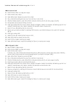


LMR-A: Manual mode
4A : Keep the LMR-A in Manual mode.
4B : Switch ON the 3-Phase incoming main supply.
4C : Switch ON the rocker switch.
4D : Amber LED will start blinking for a period of min 30sec.
4E : 30sec is the default setting which can vary from min 0.5min to max.5min.
4F : After the ON delay duration, amber LED will ON continously indicating that the incoming supply is healthy.
4G : Press the green push putton for switching ON the starter.
4H : Starter gets switched ON. Star & Line contactor switch ON simultaneously.
4I : Green LED turns ON indicating that the motor is ON.
Then after preset time of Star delta Timer, Star contactor switches OFF and Delta contactor switch ON
4J : Switch OFF the red push button for switching OFF the starter.
4K : Starter gets switched OFF.
4L : Green LED turns OFF indicating that the motor is OFF.
4M : Amber LED indication remains continous ON.
4N : Switch OFF the 3-phase incoming main supply.
4O : Amber LED indication gets turned OFF indicating that there is no incoming main supply.
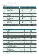
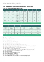
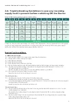
2.5: Operating procedure in normal condition
Starter operation:
Table: 11 FASD starter operating sequence in normal condition
LMR-A
Mode
Manual
Auto
Bypass
4A
3
ф
main
supply
ON
ON
ON
4B
Rocker
switch
ON
ON
ON*
4C
Amber
LED
Blink
(On-delay
duration)
Blink
(On-delay
duration)
Blink
(On-delay
duration)
4D
On-
Delay
0.5-5min
0.5-5min
0.5-5min
4E
Amber
LED
ON
ON
ON
ON
ON
ON
ON
ON
ON
4F
‘ON’ Push
button
ON
NA
ON
4G
Starter
Operation
4H
Starter
Operation
4I
ON operation
‘OFF’ Push
button
OFF
Lock
OFF
4J
Starter
Operation
OFF
OFF
OFF
OFF
OFF
OFF
OFF
OFF
OFF
OFF
OFF
OFF
4K
Green
LED
4L
Amber
LED
4M
3
ф
main supply
4N
Amber LED
indication
ON
ON
ON
4O
OFF operation
Installation, Maintenance & Troubleshooting guide
| Version 02
18
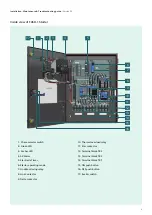
Содержание RAJA+
Страница 1: ...Installation Maintenance Troubleshooting Guide For RAJA Agriculture Starters Controllers ...
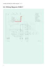
Страница 5: ...2 2 Wiring Diagram FASD 1 Installation Maintenance Troubleshooting guide Version 02 5 ...
Страница 6: ...Control logic diagram 6 Installation Maintenance Troubleshooting guide Version 02 ...
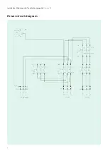
Страница 7: ...Power circuit diagram 7 Installation Maintenance Troubleshooting guide Version 02 ...
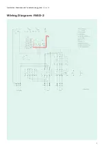
Страница 8: ...8 Wiring Diagram FASD 2 Installation Maintenance Troubleshooting guide Version 02 ...
Страница 9: ...9 Control logic diagram Installation Maintenance Troubleshooting guide Version 02 ...
Страница 10: ...10 Power circuit diagram Installation Maintenance Troubleshooting guide Version 02 ...
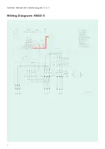
Страница 11: ...Wiring Diagram FASD 3 Installation Maintenance Troubleshooting guide Version 02 11 ...
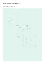
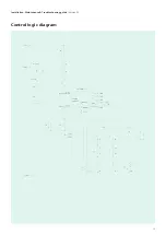
Страница 12: ...Control logic diagram 12 Installation Maintenance Troubleshooting guide Version 02 ...
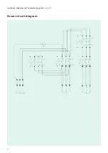
Страница 13: ...Power circuit diagram 13 Installation Maintenance Troubleshooting guide Version 02 ...