background image

Document No. 125-1902 

User Guide 

June 26, 2018 

Siemens Industry, Inc.


Page 3 of 16


Figure 1.  Controller Mounted to Ductwork. 

Outdoor, Return Air, and Mixed Air 
Sensor Operating and Mounting 
Instructions


Location and Mounting 

The Economizer Controller accepts signals from 
either the QAM2030.010 (10K, Type II) dry bulb 
temperature sensor, or 3K NTC temperature sensor. 
It provides single or differential temperature based 
economizer control or the QFM2160U combination 
temperature/humidity sensor for single or dual 
enthalpy-based economizer control. 


CAUTION/ATTENTION: 

Do not mix sensors. 
Temperature sensors must all be either 
10K Ohm Type II NTC, or 3K NTC. 
 
Ne mélangez pas de détecteurs. 
Les détecteurs de température doivent 
tous être l'un ou l'autre le Type II d'Ohm 
de 10 Ko NTC, ou 3 Ko NTC. 

 
For differential dry bulb operation, use two 
QAM2030.010 (10K Type II NTC) or 3K NTC 
temperature sensors. 


Figure 2.  3K NTC Curve. 

NOTE:

  3K NTC sensors must follow this curve. 

Sensor Mounting 

1.  Mount the sensor in any orientation, exposing it 

to freely circulating air, using the two mounting 
screws provided with the sensor. Choose a 
location that protects it from rain, snow, and 
direct sunlight. 
 

2.  Connect the appropriate Type II NTC 10K or 3K 

sensor for: 

o


Outside Air: Connect to the OAT and COM 
terminals


of the device. 

o


Return Air (Differential): Connect to the RAT 
and COM terminals of the device. 

o


Mixed Air: Connect to the MAT and COM 
terminals of the device. 


Figure 3.  Type II NTC 10K or 3K Sensor Connections. 

3.  Connect the QFM2160U Combination 

Temperature/Humidity sensor for Enthalpy 
control. 

o


Outside Air: Connect to the OAT, COM, and 
OAH terminals of the device. 

o


Return Air (Differential): Connect to the 
RAT, COM, and RAH terminals of the 
device. 


Figure 4.  QFM2160U Combination 

Temperature/Humidity Sensor Connections. 

Содержание POL220 Series

Страница 1: ...ust fan operation as well as during sensor failure Quick installation and easy commissioning Two stage cooling control Occupancy input with default capability Quick connect I O with 1 4 spade connections Anti freeze protection Brownout protection Product Numbers Economizer Controller Single Economizer Controller Multi pack 20 Remote Potentiometer Input Type POL220 05 POL220 00 BSG61 0 10 Vdc POL22...

Страница 2: ...ensing Inputs Combination Temperature Humidity Sensor QFM2160U 5 wire 18 20 or 22 AWG cable connection Dry Bulb Temperature Sensor 10K Ohm Type II NTC QAM2030 010 or 3K NTC 2 wire 18 20 or 22 AWG cable connection DCV CO2 Sensor QPA2000 3 wire 18 20 or 22 AWG cable 0 to 10 Vdc control signal Outputs Actuator GCA151 1P GMA151 1P GQD151 1P 4 wire 18 AWG Actuator Signal 2 to 10 Vdc Actuator Input Resi...

Страница 3: ...ential dry bulb operation use two QAM2030 010 10K Type II NTC or 3K NTC temperature sensors Figure 2 3K NTC Curve NOTE 3K NTC sensors must follow this curve Sensor Mounting 1 Mount the sensor in any orientation exposing it to freely circulating air using the two mounting screws provided with the sensor Choose a location that protects it from rain snow and direct sunlight 2 Connect the appropriate ...

Страница 4: ...er To power the Economizer Controller connect a 24 Vac external power supply source Figure 5 Connecting to Power Supply Source Damper Actuator Connection to the Economizer Controller 1 Connect the appropriate Siemens OpenAir Damper Actuator to the controller actuator input as shown 2 Select the appropriate modulating 2 to 10 Vdc spring return damper actuator to operate the Economizer damper See Ta...

Страница 5: ...lting Engineer defines the minimum damper position by the minimum outdoor airflow required in the building during the occupied period To determine the minimum amount of outside air to bring in the building use these basic guidelines The OA rate can be calculated by this formula OA MAT RAT OAT RAT A minimum 10 F temperature differential between OA and RA must be maintained otherwise this formula do...

Страница 6: ...r and RA temperature sensor MA temperature sensors are used Set the DIP switch to DIFF Differential mode See Figure 7 The outside air dry bulb temperature is compared with the return air dry bulb temperature If the outside air dry bulb temperature is less than the return air dry bulb temperature then the outside air is used to meet all or part of the cooling demand Control Mode 3 Combination Fixed...

Страница 7: ...tage 1 Cooling Demand Y2 is Stage 2 Cooling Demand Free Cooling is always the first cooling stage The Cool Stage 1 call from the Commercial Thermostat Y1 energizes the CC1 input to the Economizer Controller The Cool Stage 2 call from the Commercial Thermostat Y2 energizes the CC2 input to the Economizer Controller Table 4 Cooling Stage I O Logic Economizer Y1 Thermostat Y2 Thermostat Cooling Stage...

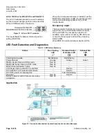
Страница 8: ...M If an occupancy signal is not available order Jumper Accessory 985 960 and connect to these inputs to default the occupancy status to ON When OFF the minimum damper position is 0 LED Fault Detection and Diagnostics Table 5 LED Pattern Summary Status Free Cooling LED Demand Control Ventilation LED Exhaust Fan LED Commissioning mode Red Blinking Red Blinking Power Start up Orange Orange Green MA O...

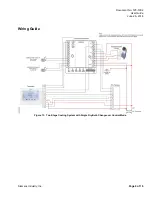
Страница 9: ...Document No 125 1902 User Guide June 26 2018 Siemens Industry Inc Page 9 of 16 Wiring Guide Figure 13 Two Stage Cooling System with Single Dry Bulb Changeover Control Mode ...

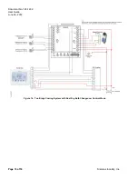
Страница 10: ...Document No 125 1902 User Guide June 26 2018 Page 10 of 16 Siemens Industry Inc Figure 14 Two Stage Cooling System with Dual Dry Bulb Changeover Control Mode ...

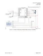
Страница 11: ...Document No 125 1902 User Guide June 26 2018 Siemens Industry Inc Page 11 of 16 Figure 15 Two Stage Cooling System with Single Enthalpy Changeover Control Mode ...

Страница 12: ...Document No 125 1902 User Guide June 26 2018 Page 12 of 16 Siemens Industry Inc Figure 16 Two Stage Cooling System with Dual Enthalpy Changeover Control Mode ...

Страница 13: ...Guide June 26 2018 Siemens Industry Inc Page 13 of 16 Figure 17 Optional CO2 Sensor and Remote Potentiometer LVC2 135 Ohm Figure 18 Optional CO2 Sensor and Remote Potentiometer BSG61 0 to 10 Vdc The installation is now complete ...

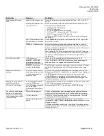
Страница 14: ... on Brownout If voltage is below 18 Volts the Economizer Controller may be in Brownout Protection mode This mode disables all of the relay outputs When the power is back to 18 Vac or higher the Economizer Controller and RTU will operate normally Y1 Y2 signal is missing from the thermostat Mechanical Cooling doesn t run until there is cooling demand Y1 Y2 Active Check the wiring from CC1 Q11 and CC...

Страница 15: ...e 0 position The DCV feature should not be enabled but it was not turned off Adjust the DCV ACT potentiometer to full CCW position if you are not using DCV Exhaust Fan LED is not working The Ex FAN potentiometer hasn t been set up correctly or has been damaged by excessive force In its full CCW position the EX FAN control is disabled therefore the Exhaust Fan LED is OFF and the EF relay is inactiv...

Страница 16: ... to the following two conditions 1 This device may not cause harmful interference and 2 this device must accept any interference received including interference that may cause undesired operation Note This equipment has been tested and found to comply with the limits for a Class B digital device pursuant to part 15 of the FCC Rules These limits are designed to provide reasonable protection against...

Отзывы: