


9
2.5 WIRING THE PAD-3
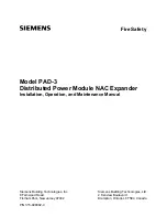
Figure 2-2 shows the general layout of the PAD-3 PC board. This section also provides specific wiring
details for accessories. Consult your control unit manual for specific wiring information on the control unit
being used. If you are using a Siemens control unit, see Section 3 for connections.
Figure 2-2. PAD-3 PC Board Layout
C A U T I O N H O T


